
A4 Mk1
 |
|
|
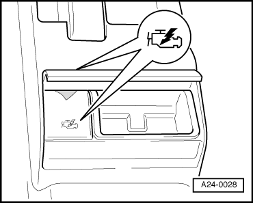
For vehicles up to Model Year 2000 → Diagnosis connection is located beneath cover in rear ashtray (centre console) for vehicles up to Model Year 2000.
For vehicles as of Model Year 2000 |
 |
|
|
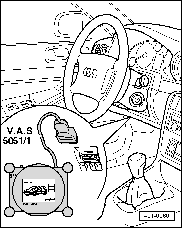
→ As of Model Year 2000 diagnosis connection is located beneath knee restraint to the left of the steering wheel. For all vehicles:
Attention:
Note: |
 |
|
|
If fault message appears on display: => Operating instructions for vehicle diagnostic, testing and information system VAS 5051
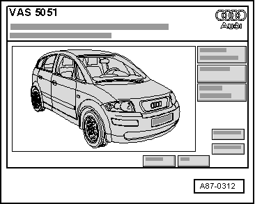
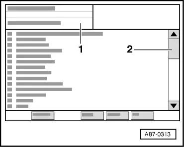
→ Display on VAS 5051:
|
 |
|
|
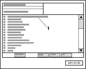
→ Display on VAS 5051: Note: Touching "00 - Interrogating fault memory - entire system" in list -1- implements the automatic test sequence, i.e. fault memory interrogation takes place for all vehicle systems with self-diagnosis capability. |
 |
|
Notes:
|
 |
|||||||||||||||||||
|
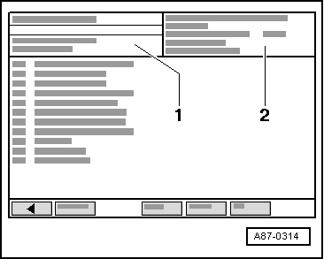
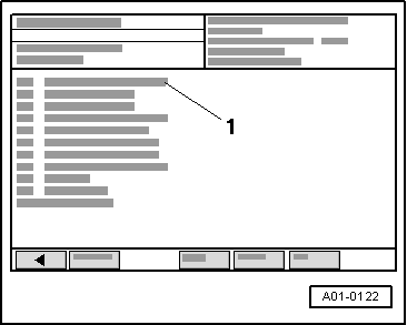
→ Display on VAS 5051:
Check the following if "Vehicle system not available" appears in zone -1- of VAS 5051 display:
=> Current Flow Diagrams, Electrical Fault-finding and Fitting Locations binder
| |||||||||||||||||||
 |
|
|