|
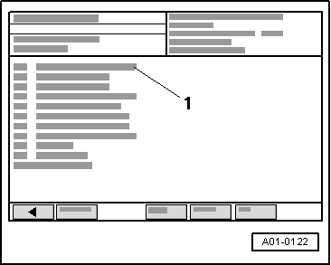
→ Display on VAS 5051:
-
‒ Select diagnosis function "06 - End of output" in list => Page 01-185.
List of display group numbers available for gearbox with hydraulic control E17
|
|
|---|
|
Display group number
|
Display zone
|
Designation
|
Explanatory notes on Page
|
|
001
|
1
2
3
4
|
Engine speed
Gearbox input speed sender -G182
Gearbox speed sender -G38
Gear engaged
|
|
|
002
|
1
2
3
4
|
Driving dynamics index
Throttle valve value
Gearbox speed sender -G38
Gear engaged
|
Test table onwards
|
|
003
|
1
2
3
4
|
Brake
"P" "N" lock
Vehicle speed
Supply voltage/pin 54, 55
|
|
Continued on next page
List of display group numbers available for gearbox with hydraulic control E17
|
|
|---|
|
Display group number
|
Display zone
|
Designation
|
Explanatory notes on Page
|
|
004
|
1
2
3
4
|
ATF temperature
Selector lever position
Multi-function switch position
On-board diagnosis information 1)
Engine intervention request 2)
|
|
|
005
|
1
2
3
4
|
Solenoid valve 1 -N88
Solenoid valve 2 -N89
Solenoid valve 3 -N90
Gear engaged
|
Test table onwards
|
|
006
|
1
2
3
4
|
Specified current of solenoid valve 4 -N91
Specified current of solenoid valve 5 -N92
Specified current of solenoid valve 6 -N93
Gear engaged
|
|
1) Vehicles with CAN bus only. For a precise definition of which vehicles are fitted with CAN bus, refer to
=> Automatic Gearbox 01V Front and Four-Wheel Drive; Repair Group 00; Code letters, assignment of mechanical units, transmission ratios, features
2) Vehicles with no CAN bus only For a precise definition of which vehicles are fitted with CAN bus, refer to
=> Automatic Gearbox 01V Front and Four-Wheel Drive; Repair Group 00; Code letters, assignment of mechanical units, transmission ratios, features
Continued on next page
List of display group numbers available for gearbox with hydraulic control E17
|
|
|---|
|
Display group number
|
Display zone
|
Designation
|
Explanatory notes on Page
|
|
007
|
1
2
3
4
|
ATF temperature
Specified current of solenoid valve 7 -N94
Torque converter clutch
Torque converter slip speed
|
Test table onwards
|
|
008
|
1
2
3
4
|
Kickdown switch
Throttle valve value
Engine torque in Nm 1)
Throttle valve duty cycle in % 2)
Overrun/"under acceleration"
|
|
1) Vehicles with CAN bus only. For a precise definition of which vehicles are fitted with CAN bus, refer to
=> Automatic Gearbox 01V Front and Four-Wheel Drive; Repair Group 00; Code letters, assignment of mechanical units, transmission ratios, features
2) Vehicles with no CAN bus only For a precise definition of which vehicles are fitted with CAN bus, refer to
=> Automatic Gearbox 01V Front and Four-Wheel Drive; Repair Group 00; Code letters, assignment of mechanical units, transmission ratios, features
Continued on next page
List of display group numbers available for gearbox with hydraulic control E17
|
|
|---|
|
Display group number
|
Display zone
|
Designation
|
Explanatory notes on Page
|
|
009 1)
|
1
2
3
4
|
Actual engine torque
Maximum torque
Engine speed
Throttle valve value
|
|
|
009 2)
|
1
2
3
4
|
Actual engine torque
Engine speed
Throttle valve value
Consumption signal
|
Test table onwards
|
|
010
|
1
2
3
4
|
Torque increase in torque converter
Engine speed
Gear engaged
Traction control system (TCS)
|
|
|
011
|
1
2
3
4
|
Selector lever position
Tiptronic recognition
Change-up/change-down position for Tiptronic switch -F189
Air conditioner kickdown
|
|
1) Vehicles with CAN bus only. For a precise definition of which vehicles are fitted with CAN bus, refer to
=> Automatic Gearbox 01V Front and Four-Wheel Drive; Repair Group 00; Code letters, assignment of mechanical units, transmission ratios, features
2) Vehicles with no CAN bus only For a precise definition of which vehicles are fitted with CAN bus, refer to
=> Automatic Gearbox 01V Front and Four-Wheel Drive; Repair Group 00; Code letters, assignment of mechanical units, transmission ratios, features
|