audi Workshop Repair Guides

Audi Workshop Service and Repair Manuals

Attaching engine to repair stand > < Removing and installing engine
4-Cyl. TDI®Engine, Mechanics
Removing and installing engine
Removing

Notes:

  • ◆ Engine must be removed without transmission from front of vehicle.
  • ◆ All cable ties unfastened or cut open on removing engine are to be re-attached in same position on installation.
  • ◆ Coolant drained off must be collected in a clean container for disposal/re-use.

Vehicles with automatic gearbox:

  • ‒ Move selector lever to position "N".
 
A20-0564

All models:

  • ‒ Heed (if necessary obtain) code for vehicles with encoded radio/radio navigation system (RNS).
  • ‒ → Remove rubber seal from front of plenum chamber cover -arrows-.
  • ‒ Remove plenum chamber cover -1- from the front.
 
A20-0513
  • ‒ → Disconnect earth strap -arrow- at battery with ignition switched off.
Attention:
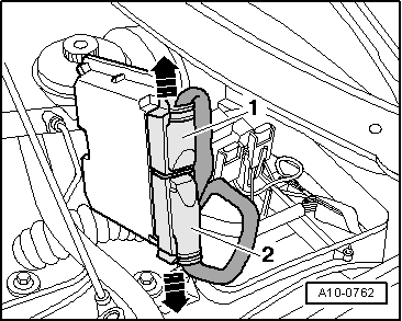
Hot vapour may escape when opening expansion tank. Cover cap with cloth and open carefully.
  • ‒ Unscrew cap of coolant expansion tank.

 
A10-0659
  • ‒ → Pull dipstick -1- out of guide tube.
  • ‒ Unclipcaps.
  • ‒ Remove nuts -arrows- and detach engine cover.
  • ‒ Remove insulation lying below.
  • ‒ Re-insert dipstick into guide tube.
 
A13-0339
  • ‒ Unclipcaps.
  • ‒ → Remove bolts -arrows- and detach air cleaner cover.

 
A10-0746
  • ‒ → Screw out bolts -arrows-.
  • ‒ Remove air duct -1- and -2-.
 
A10-0658
  • ‒ Remove front bumper:

=> General Body Repairs, Exterior; Repair Group 63; Front Bumper; Removing and installing front bumper

  • ‒ → Release quick-release fasteners -1 ... 3- and detach noise insulation (2 pieces).

 
N34-0588
  • ‒ → Unbolt noise insulation holder -arrow-.
 
A10-0345
  • ‒ → Remove air duct in front of charge air cooler -arrows-.

 
A10-0020
  • ‒ Place drip tray V.A.G 1306 below engine.
  • ‒ → Turn drain plug -arrow- at radiator anti-clockwise; attach auxiliary hose to connection if necessary.
 
A10-0347
  • ‒ → Disconnect bottom coolant hose from radiator -arrow-.
  • ‒ Detach connector -1- from radiator fan thermoswitch -F18/-F54 at bottom left of radiator and expose wire.

 
A10-0747
  • ‒ → Detach air hose -arrow- to charge air cooler at bottom left of lock carrier.
  • ‒ Detach turbocharger air hose at bottom right of lock carrier.
 
A10-0751

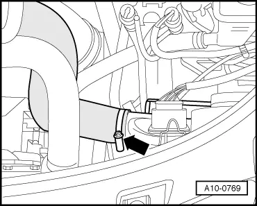
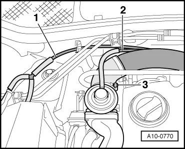
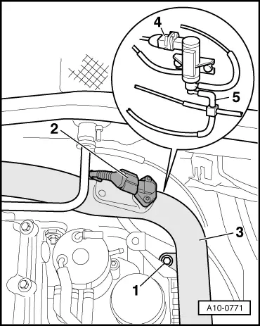
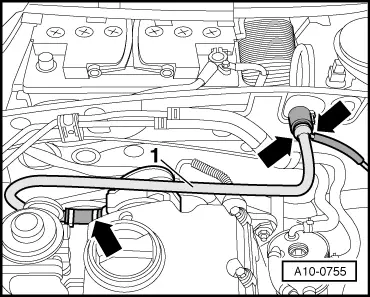
Vehicles with automatic gearbox:

Note:

Observe rules for cleanliness when working on automatic gearbox:

  • ‒ Place drip tray in position.
  • ‒ → Disconnect ATF lines -arrows-.
  • ‒ Remove bolt from holder for ATF lines at left-hand side on sump.

 
A10-0286

Vehicles with air conditioner:

  • ‒ → Where fitted, unclip green electrical connector
    -arrow- for AC compressor magnetic clutch from lock carrier at bottom right and disconnect, then expose wire.
 
A10-0752

All models:

  • ‒ → Disconnect electric headlight connector -arrow- on both sides.

 
A10-0753
  • ‒ → Disconnect electric turn signal connectors -2- on both sides.
  • ‒ Disconnect electrical connectors -1- from both horns.
  • ‒ Expose wire on right-hand side of vehicle.
 
A10-0773
  • ‒ Detach bonnet lock cable from lock carrier:

=> General body repairs, exterior; Repair Group 55; Bonnet; Removing and installing bonnet lock cable

  • ‒ Detach cover from power steering fluid reservoir.
  • ‒ → Disconnect connectors -1-, -2-, -3- and -5- in front of ABS unit and expose wires.

 
A10-0754
  • ‒ → Disconnect top coolant hose from radiator -arrow-.
 
A19-0051

Vehicles with air conditioner:

Attention:
Never open refrigerant circuit of air conditioner.

Note:

To prevent damage to condenser and refrigerant lines/hoses ensure that lines and hoses are not stretched, kinked or bent.

  • ‒ → Unbolt air ducts on left and right sides of radiator -4-.
  • ‒ Remove condenser bolts -1- and -2-.
  • ‒ Detach connector -3- from air conditioner low-pressure switch -F73.
  • ‒ Pull condenser up out of bracket, rotate towards the side and secure in place on front right wheel with wire.

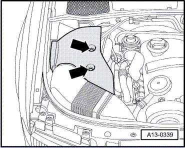
Note:

Protect wing panel from damage.

 
A10-0259

All models:

  • ‒ Unbolt lock carrier and place in a secure position.
  • ‒ → Detach coolant hoses -1- and -3-.
  • ‒ Unbolt coolant expansion tank -2- -arrows-.
  • ‒ Disconnect wiring for coolant shortage indicator switch -F66 at bottom of coolant expansion tank .
 
A10-0748
Attention:
  • ◆ The fuel system is pressurised! Before opening the system, place a cloth around the join. Then carefully detach the connection to relieve the pressure.
  • ◆ On vehicles with pump/nozzle unit engines, the temperature of the fuel lines and of the fuel may in extreme cases reach as high as 100 °C. To avoid acute danger of burns, allow fuel to cool before unfastening pipe connections.
  • ◆ Wear protective gloves.
  • ◆ Use safety goggles.
  • ‒ → Disconnect fuel supply pipe -2- from filter housing and fuel return pipe -1- from fuel cooling circuit cooler element and place aside.
 
A10-0769
  • ‒ → Detach air hose from charge air cooler-arrow-.

 
A10-0770
  • ‒ → Disconnect vent line -1- to air cleaner and vacuum line -2- to mechanical EGR valve.
  • ‒ Disconnect air hose -3- from intake manifold.
 
A10-0771
  • ‒ → Unplug connectors -2- and -4-.
  • ‒ Pull off vacuum hose -5-.
  • ‒ Screw out bolt -1-.
  • ‒ Detach air pipe -3-.

 
A10-0755
  • ‒ → Disconnect hose connections -arrows-.
  • ‒ Detach vacuum line -1-.
 
A10-0756
  • ‒ → Disconnect vent hose -2- from air cleaner housing.
  • ‒ Unplug electrical connector -4- from air-mass meter.
  • ‒ Detach EGR valve -N18 -3- from air cleaner housing and disconnect electrical connector.
  • ‒ Detach wiring harness from air cleaner housing -arrow-.
  • ‒ Detach air hose -5-.
  • ‒ Screw out bolt -1-.
  • ‒ Detach air cleaner housing.
  • ‒ Place drip tray V.A.G 1306 underneath.

 
A19-0221
  • ‒ → To drain off the remaining coolant, disconnect coolant hose -arrow- from oil cooler.
 
A10-0757
  • ‒ → Detach coolant hose to heater heat exchanger from engine -arrow-.

Notes:

  • ◆ In illustration shown on a vehicle with automatic gearbox.
  • ◆ On vehicles with manual gearbox both hoses to the heater heat exchanger must be detached.

 
A10-0758
  • ‒ → Detach coolant hoses -arrows-.
 
A10-0750

Vehicles with automatic gearbox:

  • ‒ → Detach coolant hose from EGR cooler -arrow-.

 
A10-0759

All models:

  • ‒ → Detach coolant hoses for fuel cooling circuit -arrows-.
 
A10-0760
  • ‒ → Disconnect electrical connector -4- from fuel cooling pump -V166.
  • ‒ Disconnect electrical connector -3- from charge pressure control solenoid valve -N75.
  • ‒ Disconnect vacuum hoses -1- and -2-.
  • ‒ Move wires clear.

 
A10-0761
  • ‒ → Remove electronics box cover in plenum chamber -arrows-.
 
N28-0123
  • ‒ → Carefully lever off retainer bar with screwdriver -arrow-.

 
A10-0762
  • ‒ → Release the connector lock -arrows- and disconnect connectors -1- and -2- from the control unit.
 
A10-0363
  • ‒ → Release catch -arrow- and pull auxiliary relay carrier in electronics box upwards to remove.

 
A10-0364
  • ‒ Pull off fuse 2.
  • ‒ → Release fuse box from auxiliary relay carrier and pull upwards to remove.
  • ‒ Release connector contact in connector field 2 with VAS 1978/8.
  • ‒ Disconnect connector from rear of connector rail.
 
A10-0763
  • ‒ → Unscrew earth connection -3-.
  • ‒ Remove connectors -1- and -2- from holder.
  • ‒ Disengage wiring harness -arrow- and move clear.
  • ‒ Unplug connector from speedometer sender -G22 on left of gearbox, and expose wire.

Vehicles with manual gearbox:

  • ‒ Unplug connector for reversing light switch on gearbox, and move wire clear.

 
N10-0186

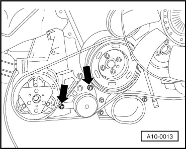
All models:

Note:

Before removing, mark direction of ribbed belt with chalk or felt-tipped pen. Running a used belt in the opposite direction could destroy it.

  • ‒ → Swivel tensioner in direction of arrow to slacken off ribbed belt.
  • ‒ Detach ribbed belt from alternator pulley.
 
A10-0764
  • ‒ Unbolt pulley of power steering vane pump. Use a mandrel as a brace.
  • ‒ → Unbolt power steering vane pump -arrow- and tie off. Leave pipes connected.

 
A10-0358
  • ‒ Unbolt cable clamp for positive wire to starter on engine at right underneath exhaust manifold.
  • ‒ → Unscrew turbocharger/catalytic converter nuts -arrows-.
  • ‒ Detach front exhaust system clamp.
  • ‒ Push clamp back to separate exhaust system.
  • ‒ Disconnect catalytic converter with exhaust pipe from turbocharger.

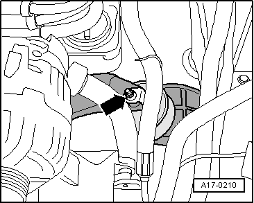
Note:

To avoid damage, decoupling element of exhaust system is never to be kinked by more than 10 °.

 
A10-0013

Vehicles with air conditioner:

Attention:
Never open refrigerant circuit of air conditioner.

Note:

Before removing, mark direction of ribbed belt with chalk or felt-tipped pen. Running a used belt in the opposite direction could destroy it.

  • ‒ → Slacken off bolts of tensioning roller for air-conditioner compressor ribbed belt -arrows-, slacken off ribbed belt and detach.
  • ‒ Detach air conditioner compressor from bracket and secure to body with wire.
 
A10-0768

All models:

  • ‒ → Slacken bolt -1- of soundproofing cover over right side drive shaft at front.
  • ‒ Unhook catch -2- and detach soundproofing cover.

 
A10-0359
  • ‒ → Unscrew earth wire from right side engine support -1-.
  • ‒ Remove bracket -2- for turbocharger -arrows-.
 
A10-0360
  • ‒ → Detach wires -1- and -2- from starter, remove insulator from positive connection on starter.
  • ‒ Unbolt cable clamp -3-.
  • ‒ Unbolt start from gearbox and detach it.

 
A10-0191

Vehicles with automatic gearbox:

  • ‒ → Remove 3 torque converter bolts through opening of removed starter using Matra V175 15 mm A/F socket attachment (rotate crankshaft by 1/3 turn each time).

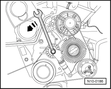
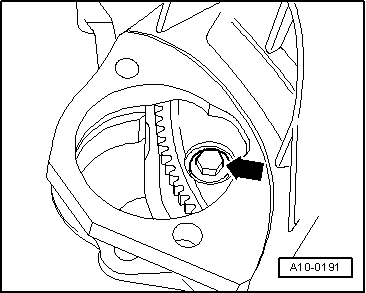
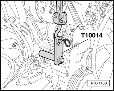
Note:

When loosening torque converter bolts, counterhold crankshaft by applying spanner to central bolt on vibration damper.

 
A10-0088

All models:

  • ‒ → Mark positions of bolted joints -1- and locating sleeves -2- underneath right and left engine mounts.

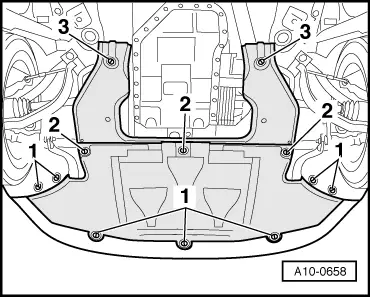
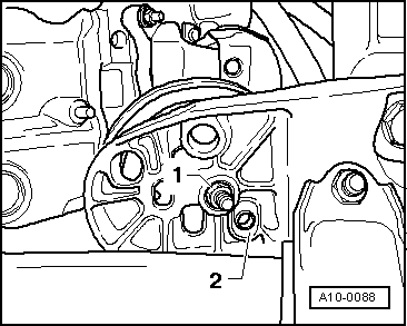
Note:

Different mounting holes are provided for different engine versions.

  • ‒ Unbolt wiring harness bracket from left side engine mount.
  • ‒ Slacken bottom nuts -1- on right and left side engine mounts a few turns.
  • ‒ Screw out engine/gearbox connecting bolts accessible from underneath.
 
A10-0017

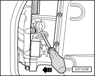
Note:

If the bolts will not unscrew:
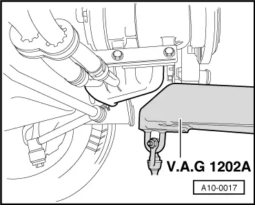
  • ‒ → Raise engine and gearbox with workshop crane V.A.G 1202 A on torque reaction support bracket.
  • ‒ Make sure no wires are damaged at the top on the bulkhead.
Attention:
To avoid injury, ensure the support is secure.
 
A17-0210
  • ‒ Lower the engine back down.
  • ‒ → Screw out the top nuts from both engine mounts.
  • ‒ Screw out engine/gearbox bolts at top. Leave one bolt screwed in hand-tight.

 
A10-0765
  • ‒ → Position support bar 10-222 A on wing mounting flange with spindle at front.

Notes:

  • ◆ To maintain sufficient clearance for the lifting tackle 3033 on the engine, the support bar 10-222 A must be placed diagonally over the front bulkhead:
    The distance between the left side foot of the support bar 10-222 A and the left side bonnet hinge must be 290 mm. The distance between the right side foot of the support bar 10-222 A and the right side bonnet hinge must be 140 mm.
  • ◆ In the illustration shown with the engine removed.
  • ‒ Attach gearbox support 3147 in bolt hole of bell housing.
  • ‒ Connect gearbox support 3147 to support bar 10-222 A using auxiliary hook 10-222 A/2.
 
A13-0348
  • ‒ → Unbolt coolant pipe brackets -1- and -2-.

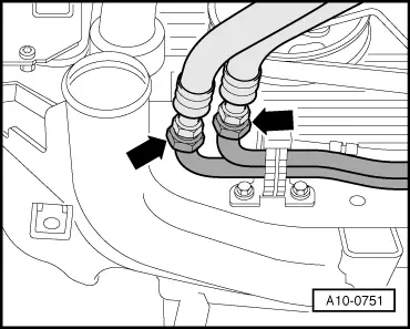
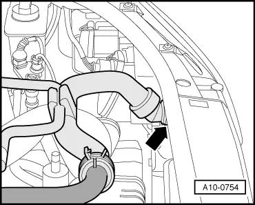
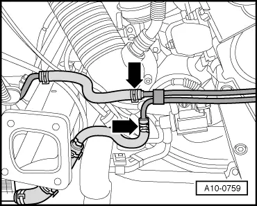
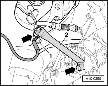
Note:

The coolant hoses can remain connected to the lines.

  • ‒ Remove top toothed belt guard -arrows-.

 
A17-0123
  • ‒ → Screw out bolts -3- and detach cover -2-.
  • ‒ Place aside charge pressure control solenoid valve -N75 -item 1- together with connected wires.
 
A10-1130
  • ‒ → Screw bracket T10014 into front of engine.

 
A10-1131
  • ‒ → Expose rear left lifting eye on engine and mount shackle 10-222 A 12.
  • ‒ Attach lifting tackle 2024 A with 2024 A/1 on engine and to workshop crane V.A.G 1202 A.

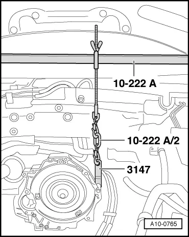
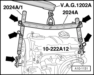
Note:

For alignment with centre of gravity of assembly, holes of support hook rails must be positioned as shown.

Attention:
Support hooks and setting pins at lifting tackle must be secured with fasteners (arrows in Fig.).
  • ‒ Screw out last bolt.

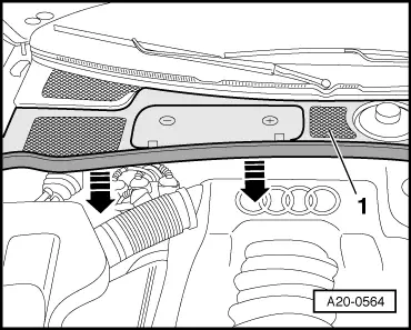
Note:

Check that all hoses and other connections between engine and body have been detached.

  • ‒ Lift engine over studs out of engine mounts.
  • ‒ Turn spindle of support bar 10-222 A.

Note:

Make sure no wires are damaged at the top on the bulkhead.

 
A37-0299

Vehicles with automatic gearbox:

  • ‒ → Separate gearbox from engine and at the same time detach torque converter from drive plate.

All models:

  • ‒ Pull engine away from gearbox and lift engine out of engine compartment from the front.

Vehicles with automatic gearbox:

  • ‒ If necessary, secure torque converter in gearbox with wire to prevent it falling out.

Attaching engine to repair stand > < Removing and installing engine