
A4 Mk1
|
Removing and installing lubrication system components
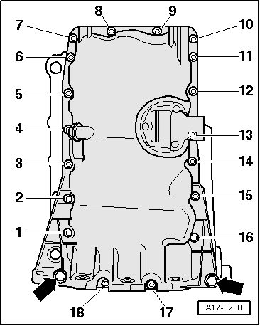
Removing and installing sump
|
 |
|
|
 |
|
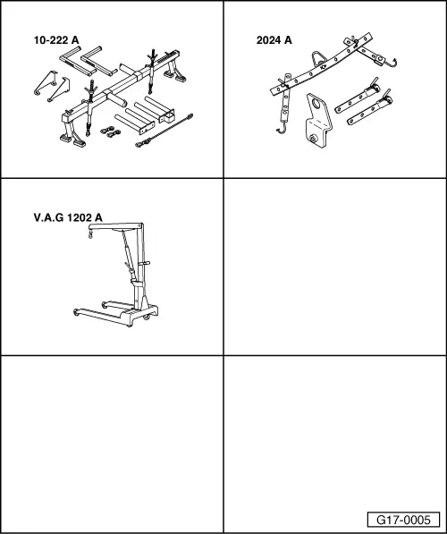
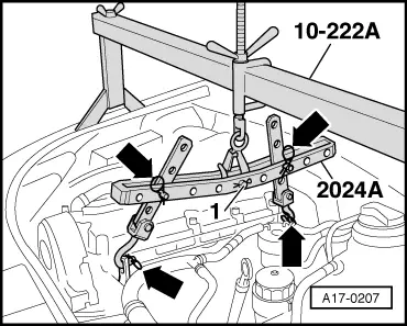
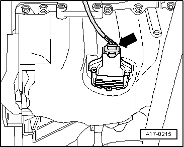
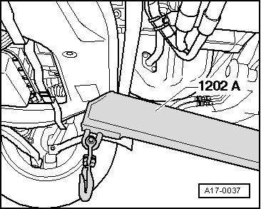
Attention:
Support hooks and setting pins at lifting tackle must be secured with fasteners (arrows in Fig.).
|
 |
|
|
 |
|
|
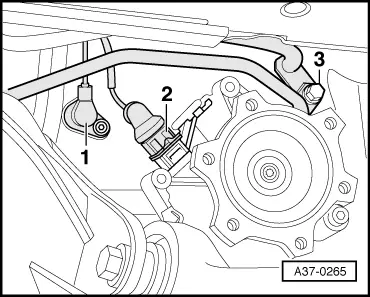
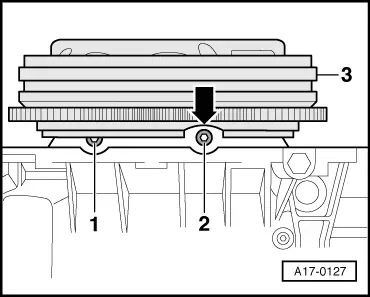
Vehicles with automatic gearbox:
Note: Observe rules for cleanliness when working on automatic gearbox: |
 |
|
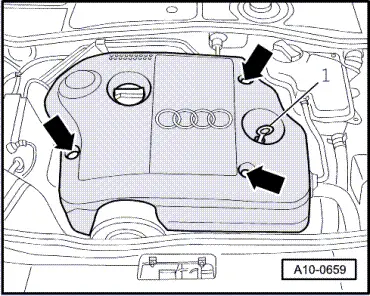
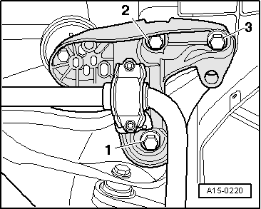
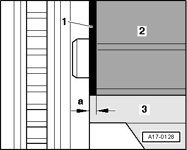
Note: Ignore -1- and -2-.
|
 |
|
|
All models:
|
 |
|
|
 |
|
|
 |
|
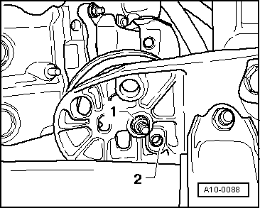
Note: Different mounting holes are provided for different engine versions.
|
 |
|
|
 |
|
Note: The subframe should be detached and lowered only at front, otherwise it will be necessary to check wheel alignment. |
 |
|
|
 |
|
|
|
|
|
 |
|
 |
|
|
Notes:
|
 |
|
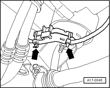
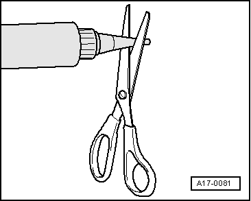
Attention:
Use safety goggles.
|
 |
|
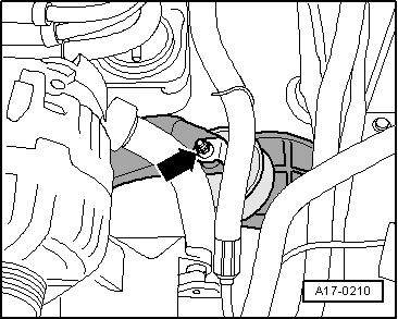
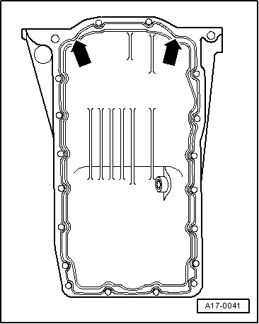
Note: Take particular care when applying sealant bead in area of rear sealing flange -arrows in Fig.-. |
|
|
 |
||||||||||||||||||||||||||||||||||
|
Notes:
Tightening torques
| ||||||||||||||||||||||||||||||||||