
A4 Mk1
|
Dismantling and assembling engine
Removing and installing toothed belt
|
 |
|
|
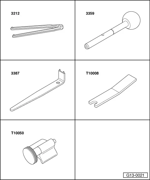
Special tools and workshop equipment required
=> Parts List |
 |
|
|
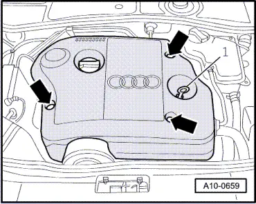
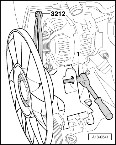
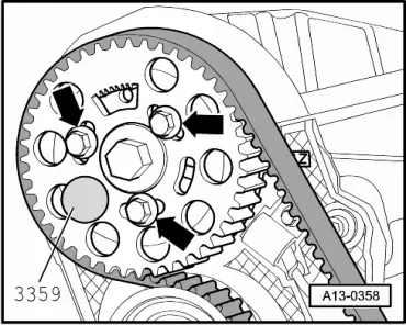
Removing
|
 |
|
|
 |
|
|
 |
|
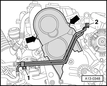
Note: The coolant hoses can remain connected to the lines.
|
 |
|
|
 |
|
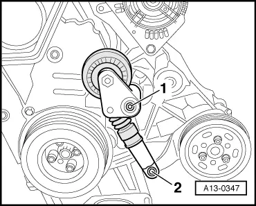
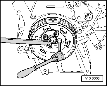
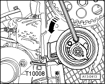
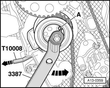
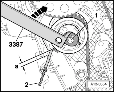
Note: Provide support with box wrench at central bolt when unfastening and tightening vibration damper. |
 |
|
|
 |
|
|
Attention:
Engine is only to be cranked by turning crankshaft in direction of engine rotation (clockwise). Note: Use central bolt of crankshaft as application point for cranking engine.
Notes:
|
 |
|
Notes:
|
 |
|
Notes:
|
 |
|
|
 |
|
|
 |
|
|
 |
|
|
|
|
|
|
|
|
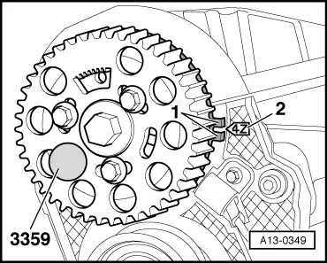
Checking valve timing
Notes:
|
|
|
Notes:
|
|
|
|
If hub cannot be locked:
Attention:
Engine is only to be cranked by turning crankshaft in direction of engine rotation (clockwise).
|
|
||||||||||||||||||||||||||||||||||
Tightening torques
1) 45°corresponds to one eighth of a turn 2) Insert with locking fluid1; => Parts List 3) Replace bolts 4) 90°corresponds to quarter of a turn | ||||||||||||||||||||||||||||||||||