audi Workshop Repair Guides

Audi Workshop Service and Repair Manuals

Extracting and driving needle bearing from/into crankshaft > < Removing and installing dual-mass flywheel/drive plate
4-Cyl. TDI®Engine, Mechanics
Removing and installing crankshaft
 
A13-0343

Note:

For performing assembly work, engine is to be attached with engine holder VW 540 to repair stand => Page 10-33.

  • Bearing shell
    • ◆ For cylinder block with oil groove
    • ◆ Do not interchange used bearing shells (mark)
  • Chain sprocket
    • ◆ For oil pump chain
    • ◆ Replacing => Page 13-82
  • Bearing shell
    • ◆ For bearing cap without oil groove
    • ◆ Do not interchange used bearing shells (mark)
 
A13-0343
  • Thrust washers
    • ◆ For bearing 3
    • ◆ Different versions for cylinder block and bearing cap
    • ◆ Note position
  • 65 Nm + further 90° (1/4) turn
    • ◆ Replace
    • ◆ For measuring radial clearance of crankshaft tighten to 65 Nm but do not give further turn
  • Bearing cap
    • ◆ Bearing cap 1: Pulley end
    • ◆ Bearing cap 3 with recesses for thrust washers
    • ◆ Retainer tabs of cylinder block/bearing cap bearing shells must coincide
 
A13-0343
  • Sender wheel
    • ◆ For engine speed sender -G28
    • ◆ Can only be fitted in one position
      -offset holes-
    • ◆ Always replace sender wheel if bolts have been unscrewed
    • ◆ Removing and installing => Fig.13-76
  • 10 Nm + further 90° (1/4) turn
    • ◆ Replace
    • ◆ Always replace sender wheel if bolts have been unscrewed => Fig.13-76
  • Needle bearing
    • ◆ On vehicles with manual gearbox
    • ◆ Extracting and driving in
      => Page 13-78
 
A13-0343
  • Fitted pin
    • ◆ Check projection from crankshaft
      => Fig.13-77
  • Crankshaft
    • ◆ Axial clearance, new: 0,07...00.23 mm
      Wear limit: 0.30 mm
    • ◆ Measure radial clearance with Plastigage
      New: 0,02...0,04 mm
      Wear limit: 0.15 mm
    • ◆ Do not turn crankshaft when measuring radial clearance
    • ◆ Crankshaft dimensions=> Page 13-81
 
A13-0150

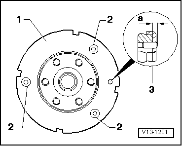
→ Fig.1    Removing and installing sender wheel

  • ‒ Always replace sender wheel -2- if bolts -1- have been unscrewed.

Notes:

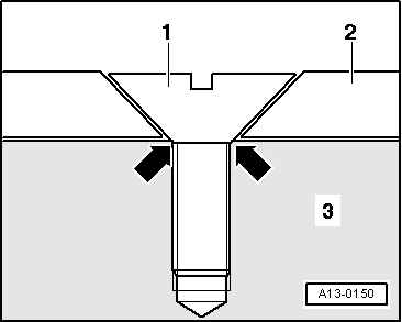
  • ◆ If the securing bolts are tightened a second time, seats for countersunk bolt heads in sender wheel will be distorted to such an extent that bolt heads will come into direct contact with crankshaft -3-
    -arrows- and sender wheel will only fit loosely under bolts.
  • ◆ It is only possible to install sender wheel in one position, mounting holes are offset.

Tightening torque

Component

Nm

Sender wheel to crankshaft

10 + 90° 1)2)

    1)    Replace bolts

    2)    90°corresponds to quarter of a turn

 
V13-1201

→ Fig. 2    Checking projection of fitted pin from crankshaft

Projection of fitted pin -3- from crankshaft

  • ◆ a =2.5...3.0 mm

Extracting and driving needle bearing from/into crankshaft > < Removing and installing dual-mass flywheel/drive plate