audi Workshop Repair Guides

Audi Workshop Service and Repair Manuals

Check intake manifold pressure sender -G71 > < Charge pressure control connection diagram
4-Cyl. TDI®Engine, Mechanics
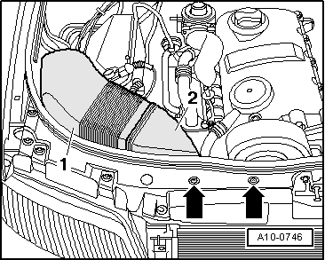
Checking charge air system with turbocharger
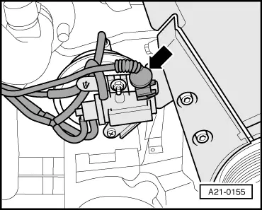
Checking charge pressure control solenoid valve -N75
 
A10-0746
  • ‒ → Screw out bolts -arrows-.
  • ‒ Remove air duct -1- and -2-.

 
A21-0155

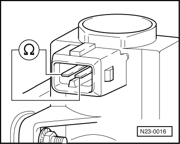
Checking internal resistance

  • ‒ Switch off ignition.
  • ‒ → Unplug connector -arrows- from charge pressure control solenoid valve.
 
N23-0016
  • ‒ → Connect multimeter to valve for resistance measurement.
    • ‒ Specification: 14 ... 20 ω

If reading does not match specification:

  • ‒ Replace charge pressure control solenoid valve -N75.

 
V96-0749

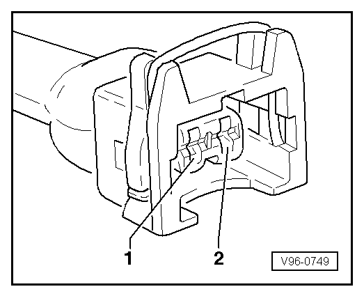
Checking power supply

  • ‒ → Connect multimeter to measure voltage between contact 2 and earth.
  • ‒ Switch on ignition.
    • ‒ Specification: Approx. battery voltage

If reading does not match specification:

  • ‒ Check for open circuit in wiring and repair if necessary.
 
V96-0749

Checking actuation

Test requirement:

  • ● Vehicle diagnostic, testing and information system VAS 5051 connected; vehicle self-diagnosis and vehicle system "01 - Engine electronics" selected
  • ‒ → Connect up voltage tester V.A.G 1527 B between contacts 1 and 2.

 
A01-0122

→ Readout on VAS 5051:

  • ‒ Enter diagnostic function "03 - Final control diagnosis" in selection -1-.
 
A01-0125
  • ‒ Actuate charge pressure control solenoid valve -N75.

→ Readout on VAS 5051:

  •     A -    3. control element being tested
  •     3 -    Charge pressure control solenoid valve-N75
    • ‒ LED must flash slowly

Note:

Voltage testers with a low current input do not go out completely between actuation of engine control unit, but rather continue to glow slightly and become distinctly brighter on actuation.

  • ‒ Terminate function "03 - Final control diagnosis" by touching ◂ key.
 
A01-0122

→ Readout on VAS 5051:

  • ‒ Enter diagnostic function "06 - End output" in selection -1-.
 
A20-0564

If LED does not respond as described:

  • ‒ → Remove rubber seal from plenum chamber cover in direction of arrow.
  • ‒ Remove plenum chamber cover -1- from the front.

 
A10-0761
  • ‒ → Remove electronics box cover in plenum chamber -arrows-.
 
N28-0123
  • ‒ → Carefully lever off retainer bar with screwdriver -arrow-.

 
A10-0762
  • ‒ → Release connector lock -arrow- and unplug connectors -1- and -2- from control unit.
 
N23-0271
  • ‒ → Connect test box V.A.G 1598/31 to cable harness connector. Actual engine control unit is not to be connected. Clip test box earthing clip onto chassis (not shown in diagram).
Attention:
So as not to destroy electronic components, select required measuring range before connecting test leads and observe test conditions.

 
V96-0749
  • ‒ → Check for open circuit and short to earth/positive in the following wiring.

Connector
Contact

Test box V.A.G 1598/31
Socket

1

62

  • ‒ If necessary, eliminate open circuit in wiring/short circuit.

Check intake manifold pressure sender -G71 > < Charge pressure control connection diagram