audi Workshop Repair Guides

Audi Workshop Service and Repair Manuals

Checking camshaft axial clearance > < Check compression
4-cylinder Diesel Direct Injection Engine (TDI), Mechanics
Servicing valve gear

Notes:

  • ◆ Cylinder heads with cracks between valve seats can still be used without a reduction of service life, if cracks are slight, max. 0.5 mm wide.
  • ◆ After installing the camshaft, wait for about 30 minutes before starting the engine. Hydraulic valve compensation elements have to settle (otherwise valves will strike pistons).
  • ◆ After working on the valve gear, turn the engine carefully at least 2 rotations to ensure that none of the valves make contact when the starter is operated.
  • ◆ Renew all gaskets and seals.
  • ◆ Note current specifications when using sealant:
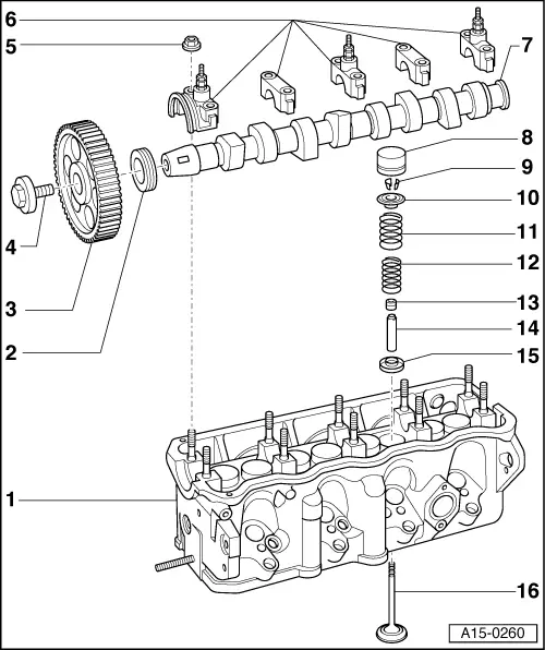
=> Parts List

 
A15-0260
  • Cylinder head
    • ◆ See note
    • ◆ Checking valve guides, grinding in valve seats
      => Page 15-60
    • ◆ Rework valve seats
      => Page 15-57
  • Sealing ring
    • ◆ Remove, to remove and install bearing cap and remove toothed belt sprocket
    • ◆ Removing and installing toothed belt=> Page 13-43
  • Camshaft sprocket
    • ◆ Remove toothed belt before removing and installing => Page 13-43
    • ◆ Release from camshaft taper by tapping with a hammer, using a drift through hole of toothed belt guard
 
A15-0260
  • 45 Nm
    • ◆ Counter hold with 3036 to loosen and tighten
  • 20 Nm
  • Bearing cap
    • ◆ Installation position => Fig.1
    • ◆ Installation sequence
      => Page 15-44, Removing and installing camshaft
    • ◆ Before installing thin coat bearing cap 1 on contact surface with "D 454 300 A2"
    • ◆ Sealing points
      => Fig.15-7
 
A15-0260
  • Camshaft
    • ◆ Check axial clearance
      => Page 15-43
    • ◆ Removing and installing
      => Page 15-44
    • ◆ Checking radial clearance with Plastigage
      Wear limit: 0.11 mm
    • ◆ Run-out: no more than 0.01 mm
    • ◆ Valve timings => from Page 00-2
  • Hydraulic bucket tappet
    • ◆ Checking => Page 15-51
    • ◆ Removing and installing
      => Page 15-54
    • ◆ Do not interchange
    • ◆ Store with cam contact surface downwards
    • ◆ Before installing check camshaft axial clearance
      => Page 15-43
    • ◆ Oil contact surface
 
A15-0260
  • Valve cotters
  • Upper valve spring retainer
  • Valve spring, outer
    • ◆ Removing and installing:
      Cylinder head
      removed: with 2037
      installed: => Page 15-54
  • Valve spring, inner
    • ◆ Removing and installing:
      Cylinder head
      removed: with 2037
      installed: => Page 15-54
  • Valve stem seal
    • ◆ Replacing => Page 15-54
  • Valve guide
    • ◆ Checking => Page 15-60
    • ◆ Replace cylinder head if wear limit exceeded
 
A15-0260
  • Lower valve spring retainer
    • ◆ Remove and install with puller 3047 A
  • Valve
    • ◆ Do not rework only grinding in is permitted
    • ◆ Valve dimensions => Fig.2
 
V15-0098

→ Fig.1    Installation position of camshaft bearing cap

Note offset. Before installing camshaft fit bearing caps and determine installation position.

 
V15-0024

→ Fig.2    Valve dimensions

Note:

Valves must not be reworked. Only grinding in is permitted.

Dim.

Inlet valve

Exhaust valve

øa

mm

35.95

31.45

øa

mm

6.963

6.943

c

mm

96.85

96.85

α

45

45

Checking camshaft axial clearance > < Check compression