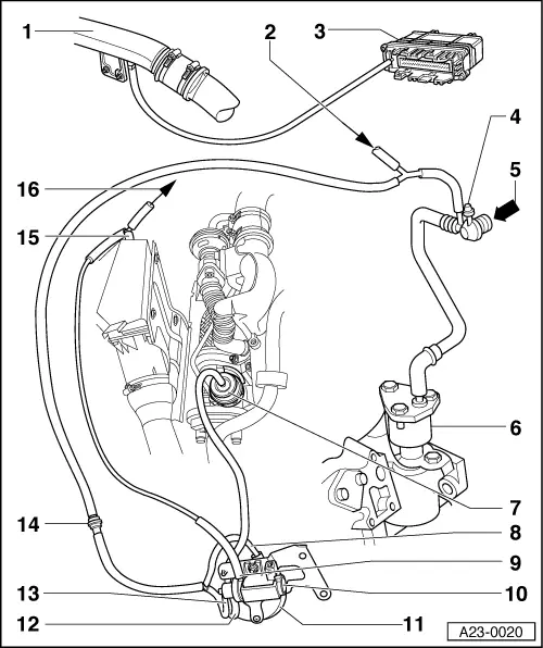
Diagram for boost pressure control - engine codes AFN, AHH
4-cylinder Diesel Direct Injection Engine (TDI), Mechanics
Charge air system with turbocharger
Diagram for boost pressure control - engine codes AFN, AHH
Note:
On vehicles 07.97 ▸ intake manifold pressure sender -G71 combined with intake manifold temperature sender -G72 is located on air duct pipe from charge air cooler to intake pipe. The connection hose shown in this illustration, from rear air duct pipe -1- to diesel direct injection system control unit -2- is therefore no longer required.
Air duct pipe, rear
◆ Boost air cooler/intake pipe
◆ ä 06.97 with pressure connection for intake manifold pressure sender -G71
From exhaust gas recirculation valve
Control unit for diesel direct injection system -J248
◆ ä 06.97 with intake manifold pressure sender -G71
Vacuum connection
◆ For air conditioner
◆ With filler cap on vehicles without air conditioner
From brake servo
Exhauster
Vacuum unit for boost pressure control
Vacuum hose
◆ To vacuum reservoir
Vent line
◆ From solenoid valve for boost pressure limitation -N75 to air cleaner.
Boost pressure control solenoid valve -N75
Vacuum reservoir
Vacuum hose
◆ From solenoid valve for boost pressure limitation -N75 to vacuum unit for boost pressure control
Vacuum hose
◆ From solenoid valve for boost pressure limitation -N75 to non-return valve
Non-return valve
◆ White connector to solenoid valve for boost pressure limitation -Fig.10- and to vacuum reservoir.