audi Workshop Repair Guides

Audi Workshop Service and Repair Manuals

Enginecrankshaft group, pistons > < Securing engine to engine and gearbox support
Installing engine
Installing engine
Procedure
  Note
t  Renew self-locking nuts and bolts.
t  Renew bolts which are tightened to a specified angle as well as oil seals, gaskets and O-rings.
t  Hose connections and air pipes and hoses must be free of oil and grease before assembly.
t  Secure all hose connections with the correct type of hose clips (same as original equipment) → Electronic parts catalogue.
t  Fit all cable ties in the original positions when installing.
   
–  Check whether dowel sleeves -A- for centring engine and gearbox are fitted in cylinder block; install missing dowel sleeves.
  A37-0075
–  Ensure that the intermediate plate is engaged on the sealing flange and pushed onto the dowel sleeves -arrows-.
Vehicles with manual gearbox:
–  Make sure that clutch plate is properly centred → Rep. Gr.30.
–  Check clutch release bearing for wear; renew if necessary.
–  Clean input shaft splines and (in the case of used clutch plates) the hub splines. Remove corrosion and apply only a very thin coating of grease for clutch plate splines -G 000 100- to the splines. Then move clutch plate back and forth on input shaft until the hub moves smoothly on the shaft. Remove any excess grease. Do not lubricate guide sleeve → Rep. Gr.30.
–  A needle bearing must be fitted in the crankshaft on vehicles with manual gearbox; install needle bearing if not already fitted → Chapter.
Vehicles with automatic gearbox:
–  In vehicles with automatic gearbox, the needle bearing must NOT be fitted in the crankshaft; remove needle bearing if fitted → Chapter.
  A10-0129
–  Checking installation depth of torque converter:
l  If the torque converter has been correctly installed, the distance between the bottom contact surfaces at the threaded holes in the torque converter and the contact surface on the torque converter bell housing (with automatic gearbox) is approx. 23 mm.
  Caution
Risk of damage to gearbox if torque converter is installed incorrectly.
If the torque converter has not been fully inserted, this distance will be approx. 11 mm.
  V32-0069
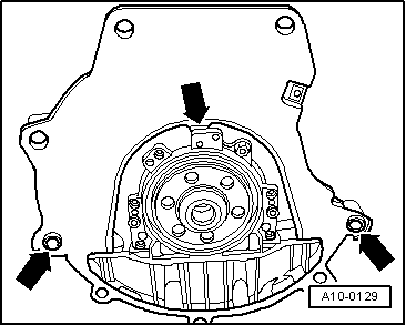
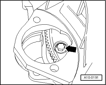
–  Before bringing engine and gearbox together, turn torque converter and drive plate on engine so that the holes for one securing bolt are in line with the opening for the starter motor -arrow-.
–  To secure torque converter on drive plate, use only new bolts (same as original equipment); refer to → Electronic parts catalogue.
  Caution
Risk of damage to gearbox if torque converter is installed incorrectly.
t  
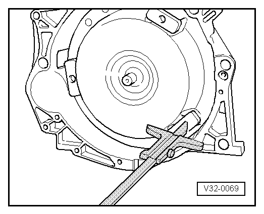
Before and during tightening of bolts securing engine to gearbox, continually check that the torque converter behind the drive plate can be turned.
t  If the torque converter cannot be turned, the drive lugs of the ATF pump and consequently the gearbox will be damaged when the bolts are finally tightened.
All vehicles (continued):
–  Join engine onto gearbox and screw in one securing bolt (tighten hand-tight).
–  Slacken spindle of support bracket -10 - 222 A-.
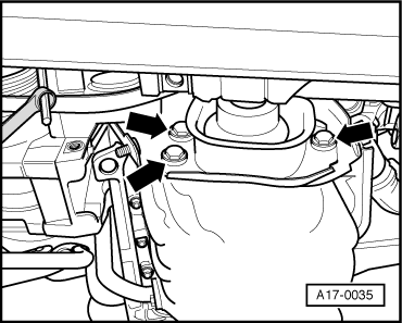
–  Lower engine, inserting studs of engine mountings into consoles for engine mountings.
–  Install engine mountings free of stress. To do so, shake engine before tightening engine mountings.
–  Install starter → Rep. Gr.27
–  Install catalytic converter → Chapter.
–  Install V-belt → Chapter.
–  Install viscous fan → Chapter.
–  Install air conditioner compressor → Rep. Gr.87.
–  Install power steering pump → Rep. Gr.48.
–  Install poly V-belt → Chapter.
–  Install lock carrier with attachments → Rep. Gr.50.
  A10-0191
–  Allow stop for torque reaction support to rest on rubber buffer for torque reaction support under its own weight, and tighten bolts.
Vehicles with automatic gearbox:
–  Secure ATF pipes → Rep. Gr.37.
Vehicles with throttle cable:
–  Adjust throttle cable → Rep. Gr.20.
All vehicles (continued):
–  Install front bumper → Rep. Gr.63.
–  Align the exhaust system so it is free of stress → Chapter.
–  Electrical connections and routing → Current flow diagrams, Electrical fault finding and Fitting locations.
  Caution
Risk of damage to control units because of excessive voltage.
Never use battery charging equipment for boost starting.
–  Observe notes on procedure for connecting the battery → Rep. Gr.27.
–  Check engine oil level → Booklet802.
–  Install coolant hoses and air hoses with screw-type clips → Fig..
–  Fit drain plug with new seal on coolant pump bearing housing and tighten → Chapter.
–  Connect coolant hose with plug-in connector → Fig..
–  Fill up with coolant → Anchor.
  Note
t  Do not use drained coolant again if:
t  the cylinder head or cylinder block have been renewed.
t  the coolant is contaminated or dirty.
Vehicles with automatic gearbox:
–  Check ATF level → Rep. Gr.37.
Tightening torques
  Note
t  Tightening torques apply only to lightly greased, oiled, phosphated or black-finished nuts and bolts.
t  Additional lubricant such as engine oil or gearbox oil may be used, but do not use lubricant containing graphite.
t  Do not use degreased parts.
t  Tolerance for tightening torques ± 15 %.
  A17-0035
Engine/gearbox connecting bolts (manual gearbox)
  A37-0075
ItemBoltNm
1, 3, 4M12x6765
2, 6M12x9065
5, 11M12x11065
7, 8 1), 9, 10M10×4545
ADowel sleeves for centralising
l  1) Vehicles up to approx. 07.96: M8 bolt; tightening torque: 25 Nm.

   
Engine/gearbox connecting bolts (automatic gearbox)
  A37-0075
ItemBoltNm
1, 8, 9, 10M10x4545
2, 3, 4, 11M12x6765
5M12x11065
6M12x9065
7M10x6045
ADowel sleeves for centralising

   
ComponentNm
Bolts/nutsM610
 M715
 M820
 M1045
 M1265
Except for the following: 
Engine mounting to subframe25
Engine support to engine mounting25
Stop for torque reaction support to bracket for torque reaction support28
Torque converter to drive plate85

   
Installing coolant hoses and air hoses with screw-type clips
  Note
To ensure that the air hoses can be properly secured at their connections, spray rust remover onto the worm thread of used hose clips before installing.
Tightening torque for
1 - Hose clip -a- for air hoses: 3.5 Nm
2 - Hose clip -b- for coolant hoses: 2 Nm
  A21-10396
Connecting coolant hose with plug-in connector
–  Remove old O-ring -2- from coolant hose -3-.
–  Lightly lubricate new O-ring with coolant and fit O-ring in coolant hose.
–  Press coolant hose onto connection -1- until it engages audibly.
–  Press coolant hose in again and then pull to check that plug-in connector is correctly engaged.
  A19-10572

Enginecrankshaft group, pistons > < Securing engine to engine and gearbox support