audi Workshop Repair Guides

Audi Workshop Service and Repair Manuals

Removing engine - engine codes ANB, APU, ARK, ATW > < Checking vacuum system
Removing engine - engine codes AEB, AJL
   
Removing engine - engine codes AEB, AJL
Special tools and workshop equipment required
t  Used oil collection and extraction unit -V.A.G 1782-
t  Workshop hoist -VAS 6100-
t  Drip tray for workshop hoist -VAS 6208-
t  15 mm socket insert -Matra V/175- for vehicles with automatic gearbox
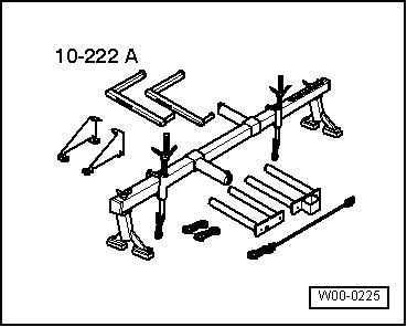
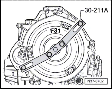
t  Support bridge -30 - 211 A- for vehicles with automatic gearbox

   
t  Support bracket -10 - 222 A-
  W00-0225
t  Lifting tackle -2024 A-
  W00-0224
t  Gearbox support -3147-
  W00-0566
t  Hose clip pliers -V.A.G 1921-
Procedure
  Note
t  The engine is removed from the front without the gearbox after removing the lock carrier.
t  Fit all cable ties in the original positions when installing.
t  Collect drained coolant in a clean container for re-use or disposal.
–  Move selector lever to position “N” on vehicles with automatic gearbox.
  W00-0464
  Caution
To prevent damage to the electronic components when disconnecting the battery:
Observe notes on procedure for disconnecting the battery.
–  Disconnect earth wire -arrow- from battery terminal → Rep. Gr.27.
  N27-0090
  WARNING
Hot steam/hot coolant can escape - risk of scalding.
t  The cooling system is under pressure when the engine is hot.
t  To allow pressure to dissipate, cover filler cap on coolant expansion tank with cloth and open carefully.
–  Open filler cap on coolant expansion tank.
  A02-0115
–  Release quick-release fasteners and remove engine cover panel -arrows-.
  A10-0661
–  Detach air cleaner cover -arrow-.
  A13-0368
–  Remove bolts -arrows-.
–  Remove air duct -1- and -2-.
–  Remove front bumper → Rep. Gr.63.
  A10-0746
–  Release fasteners -arrows- and remove noise insulation.
  A10-0018
–  Unbolt bracket for noise insulation -arrow-.
  N34-0588
–  Remove air duct in front of charge air cooler -arrows-.
  A10-0345
–  Detach cooling pipe for power steering hydraulic fluid -arrows- and move clear; do not open hydraulic fluid circuit.
–  Tighten bracket for outside temperature sensor back on finger-tight.
  N19-0152
–  Place drip tray for workshop hoist -VAS 6208- beneath engine.
–  Turn drain plug -arrow- on radiator anti-clockwise, if necessary fit drain hose to connection.
  A10-0189
–  Lift retaining clip and disconnect coolant hose (bottom) from radiator -arrow-.
–  Unplug electrical connector -1- at radiator fan thermal switch -F18/F54- at radiator (bottom left) and move wiring clear.
  A10-0347
–  Also open drain plug -arrow- on coolant pump bearing housing.
–  Remove coolant hose from hose connection at thermostat.
  N19-0154
–  Detach air hose going to charge air cooler at lock carrier (bottom left) -arrow-.
–  Detach air hose going to turbocharger from lock carrier (bottom right).
  A10-0747
Vehicles with automatic gearbox:
  Note
Observe rules for cleanliness when working on automatic gearbox → Rep. Gr.37.
–  Position used oil collection and extraction unit -V.A.G 1782- below connection point.
–  Disconnect ATF pipes -arrows-.
–  Detach bracket for ATF pipes (left-side) from engine.
  A10-0751
Vehicles with air conditioning:
–  Unclip and disconnect green electrical connector -arrow- for magnetic clutch of air conditioner compressor at lock carrier (bottom right) and move wiring clear.
  A10-0286
All vehicles (continued):
–  Unplug connectors for headlights and headlight adjustment -arrows-.
–  Turn bulb holders for turn signals anti-clockwise and remove from turn signal housing -left arrow- (both sides of vehicle).
  A10-0021
–  Lift retaining clip -arrow- and disconnect coolant hose (top left) from radiator.
–  Detach cable for bonnet at lock carrier → Rep. Gr.55.
  A10-0786
–  Remove cover -arrow- at power steering fluid reservoir.
  A10-0266
–  Unplug electrical connectors -arrows-.
–  Move electrical wiring clear.
–  Unplug connector for anti-theft alarm on lock carrier (top left) and move wiring clear.
  A10-0022
–  Unplug electrical connectors on both horns -1- and -2-, detach wiring at bracket -arrow- and move wiring clear.
Vehicles with air conditioning:
  WARNING
Risk of injury caused by refrigerant.
The air conditioner refrigerant circuit must not be opened.
  Caution
Make sure that condenser and refrigerant pipes and hoses are not damaged.
Do NOT stretch, kink or bend refrigerant lines and hoses.
  A10-0346
–  Remove bolts -4- (left and right) for air cowls from radiator.
–  Remove bolts -1 and 2- for condenser.
–  Unplug electrical connector -3- at air conditioner pressure switch -F129-.
–  Pull condenser up out of its bracket, pivot to side and secure to right-side front wheel with wire.
  Note
Protect side panel (front) from damage.
All vehicles (continued):
–  Unbolt and remove lock carrier. Place clear of vehicle and ensure that it cannot tip over.
  A19-0051
–  Unplug electrical connectors:
1 - On charge pressure control solenoid valve -N75-
2 - On activated charcoal filter solenoid valve 1 -N80-
3 - On output stage -N122-
4 - On air mass meter -G70-
–  Move wiring harness clear and lay on top of engine.
–  Detach hose connections and remove air cleaner housing -arrows-.
  A10-0215
USA models:
–  Disconnect vacuum line leading to fuel system diagnostic pump -V144--arrow-.
  A20-0291
All vehicles (continued):
–  Detach coolant hoses -1- and -3-.
–  Remove bolts -arrows-.
–  Unplug electrical connector at coolant shortage indicator switch -F66- and detach coolant expansion tank -2-.
–  Detach coolant hose (left-side) going to heat exchanger from coolant pipe (bottom) on engine.
–  Disconnect coolant hose (right-side) going to heat exchanger at cylinder head connection.
  A10-0259
Vehicles with cruise control system:
–  Disengage operating rod at throttle valve module -J338-.
–  Detach vacuum hose at vacuum unit.
All vehicles (continued):
–  Detach throttle cable from throttle valve module -J338- and from support bracket -arrows- (do not remove retainer). Move throttle cable clear to the side.
–  Remove air hose -1-.
  WARNING
The fuel system is pressurised. Before opening the system place a clean cloth around the connection. Then release pressure by carefully loosening the connection.
  A10-0216
–  Disconnect fuel supply line -1- and fuel return line -2- and move clear.
–  Disconnect vacuum hoses:
3 - To brake servo
4 - To activated charcoal filter solenoid valve 1 -N80-
  Note
On vehicles with automatic gearbox, disconnect vacuum hose -3- behind suction-jet pump.
  A10-0218
–  Remove cover for electronics box in plenum chamber -arrows-.
  A10-0024
–  Carefully lever out retaining strap using a screwdriver -arrow-.
  N28-0123
–  Release retainer catches and unplug electrical connectors -3 and 4- from engine control unit.
–  Unplug electrical connectors at altitude sender -F96--1- and at connector point -2-.
–  Unhook wiring harness -arrow- and move it clear.
  A10-0220
Vehicles with automatic gearbox:
–  Unplug electrical connector at kickdown switch -arrow-.
  A20-0229
All vehicles (continued):
–  Detach electrical connector -arrow- for Lambda probe from bracket, unplug and move wiring clear.
  A34-0124
–  Unscrew earth wire -2-.
–  Unbolt bracket for connectors -1- from plenum chamber.
–  Disengage wiring harness -arrows- and move it clear.
–  Unplug electrical connector from speedometer sender -G22- on left of gearbox, and move wire clear.
Vehicles with manual gearbox:
–  Unplug electrical connector for reversing light switch -F4- from gearbox and move electrical wire clear.
All vehicles (continued):
  Caution
If a used belt runs in the opposite direction when it is refitted, this can cause breakage.
Before removing, mark direction of rotation of poly V-belt with chalk or felt-tipped pen for re-installation.
  A10-0221
Vehicles with air conditioning:
–  Loosen bolts on tensioner for poly V-belt for air conditioner compressor -arrows-, slacken belt and remove.
  WARNING
Risk of injury caused by refrigerant.
The air conditioner refrigerant circuit must not be opened.
–  Detach air conditioner compressor from bracket and secure to body with wire.
  A10-0013
All vehicles (continued):
–  To slacken poly V-belt turn tensioner in direction of -arrow-.
–  Remove poly V-belt from pulley on alternator.
  A13-0125
–  Use M5x60 mm bolt to lock poly V-belt pulley for viscous fan and unscrew using hexagon key.
–  Take off poly V-belt.
  A10-0026
–  Remove V-belt pulley for coolant pump; apply drift -arrow- at power steering pump pulley.
–  Detach V-belt.
–  Remove poly V-belt pulley for power steering pump.
–  Unbolt power steering pump and tie up to one side; the hydraulic fluid hoses/pipes remain connected.
  A10-0256
–  Remove nuts -arrows- securing catalytic converter to turbocharger.
  A10-0791
–  Unbolt bracket for exhaust system -arrow-.
  Caution
Avoid damage to flexible joint.
t  Do not bend flexible joint more than 10°.
t  Install flexible joint so that it is not under tension.
t  Take care not to damage wire mesh on flexible joint.
–  Disconnect exhaust pipe from turbocharger.
  A10-0792
–  Detach electrical wires -1 and 2- at starter; remove insulator from positive connection on starter.
–  Remove retaining clip -4-.
–  Remove bracket for starter from cylinder block -3- and from starter.
–  Remove starter from gearbox.
–  Remove earth cable from engine support (right-side).
  A10-0223
Vehicles with automatic gearbox:
–  Unscrew 3 torque converter bolts through starter opening using  15 mm socket insert -Matra V/175- (turn crankshaft 1/3 turn each time).
  Note
When loosening torque converter bolts, counterhold at the toothed belt sprocket.
  A10-0191
All vehicles (continued):
–  Loosen top nuts -arrow- on engine mountings (right and left) several turns.
  A17-0210
–  Mark position of nuts -1- and locating sleeves -2- on bottom of engine mountings (right and left).
  Note
Different mounting holes are provided for the different engine versions.
–  Remove nut for engine mounting -1- on both sides.
  A10-0088
–  Raise engine and gearbox using workshop hoist.
  WARNING
Injury risk.
Ensure adequate support.
  Note
Make sure no wires/pipes are damaged at the top on the bulkhead.
–  Remove bolts (accessible from below) securing engine to gearbox.
–  Lower engine again.
  A10-0017
–  Position support bracket -10 - 222 A- behind gas-filled strut on bolted flanges of wing panels. The spindle must be at the front.
–  Insert gearbox support -3147- into bolt hole in gearbox bell housing.
–  Connect gearbox support -3147- to support bracket -10 - 222 A- using hooks -10 - 222 A /2-.
  Note
Shown in illustration with engine removed.
–  Unscrew top engine/gearbox securing bolts; leave one bolt in place (hand-tight).
  A10-0224
–  Engage lifting tackle -2024 A- on engine and workshop hoist.
  Note
To adjust to the centre of gravity of the assembly, the perforated rails of the support hooks must be positioned as shown.
  WARNING
Accident risk from loose components of lifting tackle.
The support hooks and retaining pins on the lifting tackle must be secured with locking pins -arrows-.
–  Remove remaining bolt securing engine to gearbox.
  Note
Check that all hoses and other connections between engine and body have been detached.
–  Raise engine with workshop hoist until the studs of the engine mountings are clear.
–  Tighten spindle of support bracket -10 - 222 A- further.
  A10-0794
Vehicles with automatic gearbox:
–  Separate gearbox from engine and at the same time detach torque converter from drive plate.
All vehicles (continued):
–  Separate engine from gearbox and guide engine forwards out of engine compartment.
  A37-0299
Vehicles with automatic gearbox:
–  Secure the torque converter in the gearbox using support bridge -30 - 211 A- to prevent it falling out.
  N37-0702

Removing engine - engine codes ANB, APU, ARK, ATW > < Checking vacuum system