| –
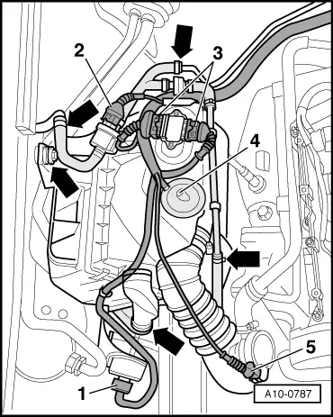
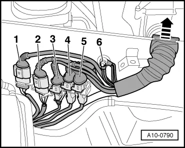
| Unscrew earth wire -6-. |
| –
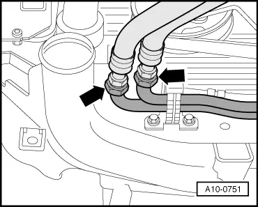
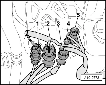
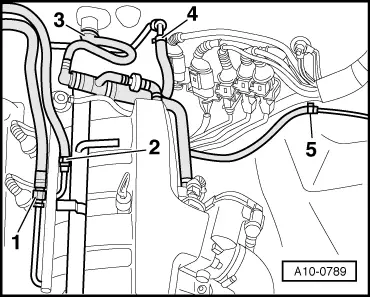
| Detach electrical connectors -1 ... 5- from bracket. |
| –
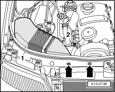
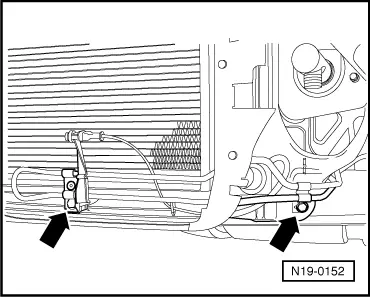
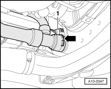
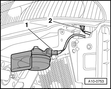
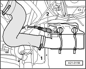
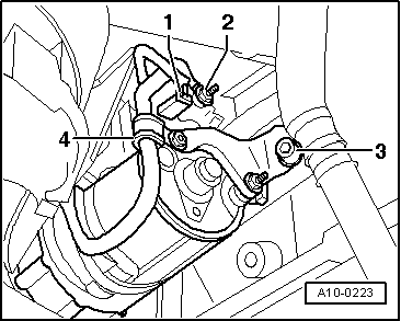
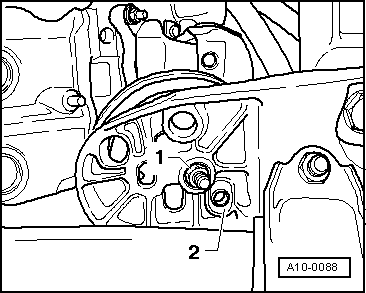
| Unplug electrical connectors: |
| 1 - | For Lambda probe after catalytic converter -G130- (brown, vehicles with 2 Lambda probes) |
| 2 - | For Lambda probe -G39- (before catalytic converter; black) |
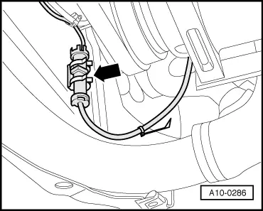
| –
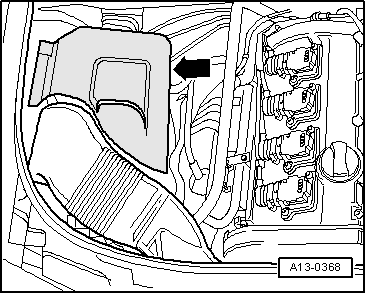
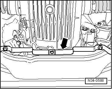
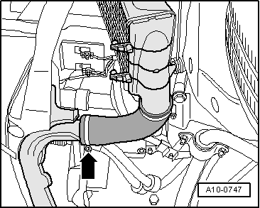
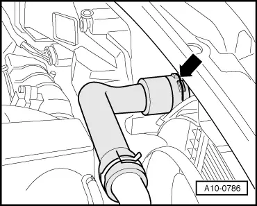
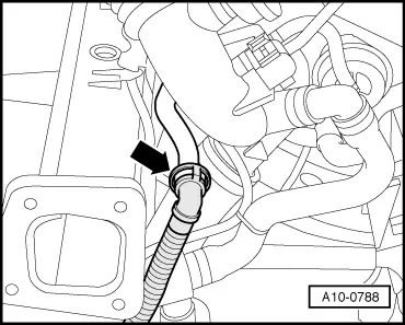
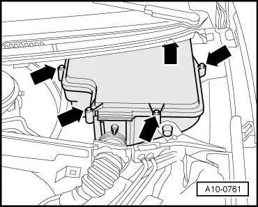
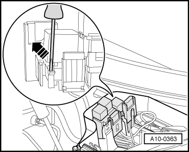
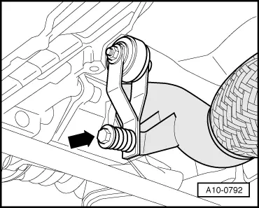
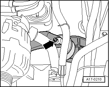
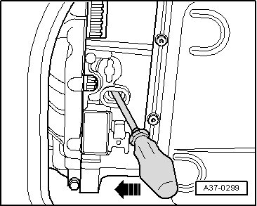
| Unhook wiring harness -arrow- and move it clear. |
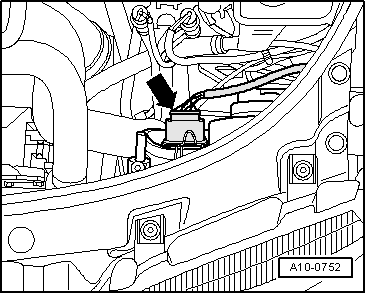
| –
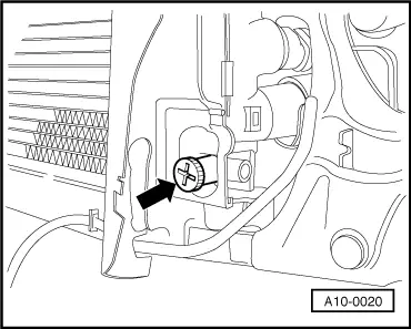
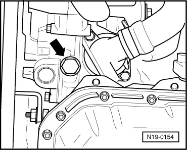
| Unplug electrical connector from speedometer sender -G22- on left of gearbox, and move wire clear. |
| Vehicles with manual gearbox: |
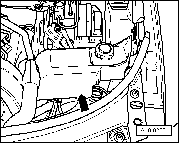
| –
| Unplug electrical connector for reversing light switch -F4- from gearbox and move electrical wire clear. |
| All vehicles (continued): |

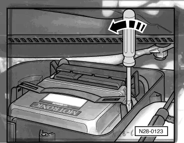
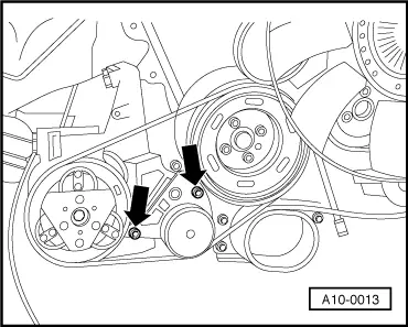
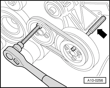
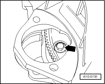
Caution | If a used belt runs in the opposite direction when it is refitted, this can cause breakage. |
| Before removing, mark direction of rotation of poly V-belt with chalk or felt-tipped pen for re-installation. |
|
|
|
|


 Note
Note
 WARNING