audi Workshop Repair Guides

Audi Workshop Service and Repair Manuals

Checking hydraulic bucket tappets > < Renewing inlet camshaft oil seal
Removing and installing camshafts and hydraulic chain tensioner
   
Removing and installing camshafts and hydraulic chain tensioner
Special tools and workshop equipment required
t  Counterhold tool -3036-
t  Chain tensioner retainer -3366-
t  Locking pin -T40011- for vehicles from 06.1999 onwards

   
Removing
l  Lock carrier must be in service position → Rep. Gr.50.
–  Release quick-release fasteners and remove engine cover panel -arrows-.
–  Remove poly V-belt and tensioner for poly V-belt → Chapter.
  A10-0661
–  Remove toothed belt cover (top section)
  Caution
Irreparable damage can be caused if the toothed belt slips.
Turn crankshaft only in direction of engine rotation (in clockwise direction).
–  Rotate crankshaft to “TDC” by turning bolt for toothed belt sprocket.
l  Marking on camshaft sprocket and marking on crankshaft must be aligned to “TDC”-arrows-.
–  Remove cylinder head cover → Chapter.
  A15-0024
Vehicles up to 05.1999:
–  Loosen TORX bolt -bottom arrow- and press toothed belt tensioner down.
–  Remove toothed belt from camshaft sprocket.
  A13-0011
Vehicles from 06.1999 onwards:
  Caution
Risk of damage to toothed belt tensioner.
The toothed belt tensioner is oil-damped and can therefore only be compressed slowly by applying constant pressure.
–  Applying constant and moderate force, apply hexagon key through opening -2- to press toothed belt tensioning roller -1- anti-clockwise -arrow- until piston can be locked with locking pin -T40011-.
–  Insert locking pin -T40011- and make sure that it remains in place.
  Note
Bolt -3- must not be slackened.
–  Remove toothed belt from camshaft sprocket.
  A13-0096
All vehicles (continued):
–  Turn crankshaft approx. 45° anti-clockwise at bolt for toothed belt sprocket so that all pistons are clear of “TDC” position.
–  Loosen camshaft sprocket bolt using counterhold tool -3036-.
–  Pull off camshaft sprocket.
–  Remove cylinder head cover → Chapter.
–  Detach oil deflector.
  A13-0381
–  Unplug electrical connector -arrow- at Hall sender -G40-.
–  Remove Hall sender → Item, → Item and → Item.
  A15-0128
–  Check “TDC” position of camshafts again:
l  The two markings on the camshafts must be in line with the two arrows on the bearing caps -arrows-.
  A15-0213
If old drive chain is to be reused:
–  Clean drive chain and sprockets of camshafts opposite the two arrows on the bearing caps and mark installation position with a coloured dot.
l  The distance between the two arrows (and thus between the coloured markings) is 16 rollers on the chain.
l  Notch on exhaust camshaft has a slight inward offset with respect to chain roller -1-.
  Note
Do not mark chain with a centre punch or by making a notch or similar.
  A15-0193
Continued for all drive chains:
–  Secure hydraulic chain tensioner with chain tensioner retainer -3366-.
  Note
Over-tightening the chain tensioner retainer can damage the hydraulic chain tensioner.
  A15-0017
–  First remove bearing caps -3 and 5- on inlet and exhaust camshafts.
–  Remove double bearing cap.
–  Remove both bearing caps next to chain sprockets on inlet and exhaust camshafts.
–  Remove bolts for hydraulic chain tensioner.
–  Slacken off bearing caps -2 and 4- on inlet and exhaust camshafts alternately in diagonal sequence, and remove.
–  Remove inlet and exhaust camshafts with hydraulic chain tensioner.
  A15-0199
Installing
l  Pistons must not be at TDC.
–  Renew rubber/metal gasket for hydraulic chain tensioner and apply a thin coat of sealant to hatched area; for sealant refer to → Electronic parts catalogue.
  A15-0027
–  Position drive chain as follows on camshaft chain sprockets:
If old drive chain is to be reused:
–  Align coloured marks -arrows-.
  A15-0212
If new drive chain is being used:
  Caution
t  The stated number of rollers merely provides assistance for fitting the drive chain onto the camshafts.
t  Make sure that the arrows on the bearing caps and the notches on the camshafts align when installing camshafts (with drive chain) in cylinder head → Anchor.
l  The distance between notches -A and B- on the camshafts must be 16 drive chain rollers. The illustration shows the exact positions of the 1st and 16th rollers on the sprockets.
l  Notch -A- is offset slightly inwards in relation to chain roller -1-.
Continued for all drive chains:
–  Insert hydraulic chain tensioner inside drive chain (2nd mechanic required).
–  Place camshafts with drive chain and hydraulic chain tensioner in cylinder head.
–  Oil running surfaces of both camshafts.
l  Dowel sleeves for bearing caps and hydraulic chain tensioner must be located in cylinder head.
  Note
When installing bearing caps ensure that the identification mark is readable from the inlet side of cylinder head.
–  Secure hydraulic chain tensioner (pay attention to dowel sleeves).
  A15-0207
–  Tighten bearing caps -2 and 4- on inlet and exhaust camshafts alternately and in diagonal sequence (pay attention to dowel sleeves).
–  Install both bearing caps next to chain sprockets on inlet and exhaust camshaft.
–  Remove chain tensioner retainer -3366-.
  A15-0199
–  Check that camshafts are positioned correctly:
l  The two marks on the camshafts must be opposite the two arrows on the bearing caps -arrows-.
  Note
If necessary, turn camshaft slightly backwards or forwards so that the two marks coincide.
  A15-0213
–  Apply a small quantity of sealant to hatched area on double bearing cap and on outer bearing cap adjacent to chain tensioner; for sealant refer to → Electronic parts catalogue.
–  Install remaining bearing caps (pay attention to dowel sleeves).
–  Renewing camshaft oil seals: → Chapter „Renewing exhaust camshaft oil seal“ or → Chapter „Renewing inlet camshaft oil seal“.
–  Secure remaining bearing caps.
  A15-0028
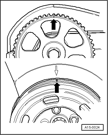
–  Install camshaft sprocket.
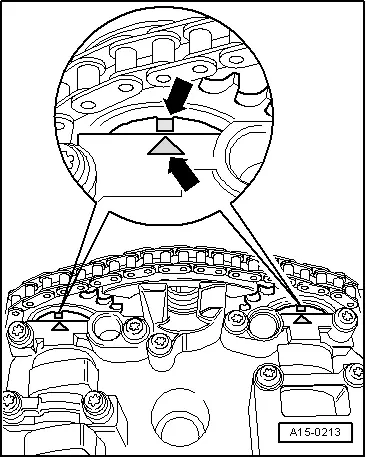
l  
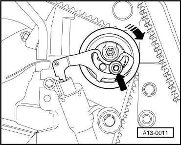
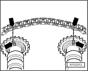
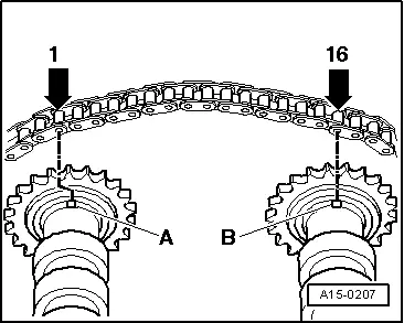
Installation position: The thinner web of the camshaft sprocket faces outwards -arrows- and the marking for “TDC” is visible.
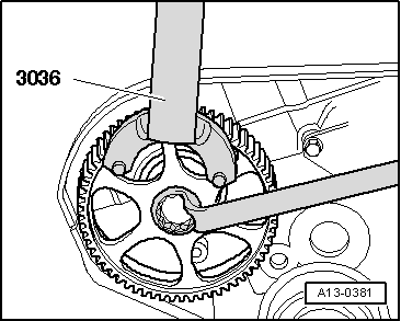
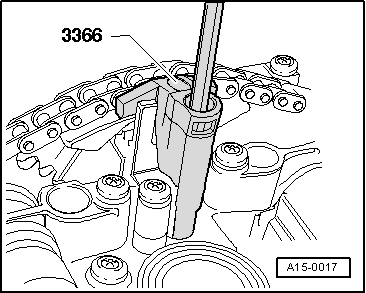
–  Tighten camshaft sprocket bolt using counterhold tool -3036-.
–  Install Hall sender → Item, → Item and → Item.
–  Install cylinder head cover → Chapter.
–  Turn crankshaft approx. 45° clockwise to “TDC” position via toothed belt sprocket bolt.
–  Install toothed belt (adjust valve timing): vehicles up to 05.1999 → Anchor, vehicles from 06.1999 onwards → Anchor.
–  Install poly V-belt → Chapter.
  Note
t  After installing camshafts, wait for approx. 30 minutes before starting engine. Hydraulic valve compensation elements have to settle (otherwise valves will strike pistons).
t  After working on the valve gear, turn the engine carefully at least 2 rotations to ensure that none of the valves make contact when the starter is operated.
Tightening torques → Chapter
  A13-0168

Checking hydraulic bucket tappets > < Renewing inlet camshaft oil seal