| t
| Adapter -V.A.G 1598/19- (engine codes AEB, AJL up to 06.96) |
| t
| Adapter -V.A.G 1598/22- (engine codes AEB, AJL from 07.96 onwards) |
| t
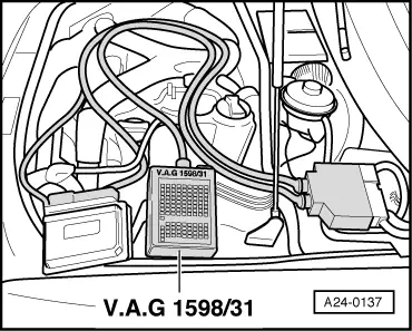
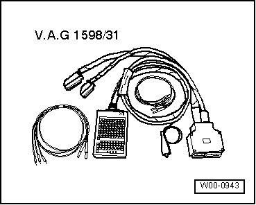
| Adapter cable, 121-pin -V.A.G 1598/31- (engine codes ANB, APU, ARK, ATW) |
| t
| Vehicle diagnostic, testing and information system -VAS 5051B- |

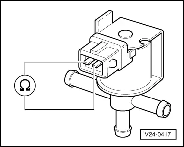
Note | The charge pressure control solenoid valve -N75- and its wiring are monitored by the engine control unit. |
| l
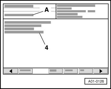
| Vehicle diagnostic, testing and information system -VAS 5051B- connected. |
| l
| Vehicle self-diagnosis and vehicle system “01 - Engine electronics” selected. |
|
|
|