audi Workshop Repair Guides

Audi Workshop Service and Repair Manuals

Removing and installing intake manifold > < Removing and installing cylinder head cover
Removing and installing cylinder head
   
Removing and installing cylinder head
Special tools and workshop equipment required
t  Counterhold tool -3415-
t  Guide pin -3450-
t  Hose clip pliers -V.A.G 1921-
t  Spark plug connector pliers -V.A.G 1922-
t  Special wrench, long reach -T10070-

Removing
  Note
t  Fit all heat insulation sleeves in the original position when installing.
t  All cable ties which are released or cut open when removing must be fitted in the same position when installing.
t  If engine oil is contaminated, perform oil change.
   
–  Detach rubber seal from plenum chamber cover in direction of -arrow-.
–  Detach plenum chamber cover -1- towards the front.
  Caution
Observe notes on procedure for disconnecting the battery → Rep. Gr.27.
  A27-0088
–  With ignition switched off, disconnect battery earth cable -arrow-.
  N27-0090
–  Remove engine cover panel -1-.
–  Remove air cleaner cover -2-.
–  Move lock carrier to service position → Rep. Gr.50.
–  Remove poly V-belt → Chapter.
–  Drain off coolant → Chapter.
  A10-0983
–  Unbolt bracket for exhaust system -arrow-.
  Note
  A10-0792
To avoid any damage, the flexible joint in the front exhaust pipe must not be bent more than 10°.
–  Loosen bolt connections of front clamp -arrows-.
–  Push the clamp back in order to separate the exhaust system.
  V26-0733
–  Unplug electrical connectors -3- and -5- for active charcoal filter system solenoid valve 1 -N80- and air mass meter -G70-.
–  Detach active charcoal filter system solenoid valve 1 -N80--item 2- from air cleaner housing.
–  Disconnect hose connection going to secondary air pump -arrow-.
–  Release hose clip -4- for air pipe at air mass meter -G70-.
–  Unscrew bolt -1- and remove air cleaner housing.
  A10-1809
–  Detach hose -2- leading to exhaust gas recirculation valve -N18-.
–  Detach crankcase breather hose -4- from air pipe.
–  Loosen hose clip -3- to remove air pipe.
  Note
Disregard -item 1-.
  A10-10330
–  Unscrew nuts -arrows- securing exhaust manifold/catalytic converter.
–  Detach exhaust system from exhaust manifold.
  A10-1074
–  Pull back heat insulation sleeve and disconnect hose from secondary air pipe by pressing release tabs -arrows-.
–  Remove bolt -1-.
  A15-1001
–  Unplug electrical connector -1- at Hall sender -G40-.
  Note
Disregard items marked -2-, -3- and -arrows-.
  A15-1057
–  Unplug electrical connector -3- at exhaust gas recirculation valve -N18- and move wiring harness clear.
–  Remove bolts -1- and -4-.
–  Detach exhaust gas recirculation valve -N18-.
  Note
t  Disregard -item 2-.
t  Shown from rear with engine removed for illustration purposes.
  A26-10020
–  Detach rear coolant hose -1- from cylinder head.
–  Unplug electrical connector -2- at coolant temperature sender -G62-.
–  Remove bolt -3-.
–  Move wiring harness clear.
  Note
Shown from rear with engine removed for illustration purposes.
–  Remove coolant pipe (top) → Chapter.
–  Remove intake manifold (top section) → Chapter.
–  Detach spark plug connectors using spark plug connector pliers -V.A.G 1922-.
  A15-10168
–  Remove toothed belt from camshaft sprocket → Chapter.
–  Unscrew nut -arrow- for tensioning roller.
–  Remove washer and tensioning roller.
  A13-0504
–  Loosen camshaft sprocket using counterhold -3415-.
–  Detach camshaft sprocket.
–  Remove parallel key from camshaft.
  N15-0455
–  Unbolt toothed belt cover (rear) from cylinder head -arrows-.
  A15-0906
–  Remove crankcase breather hose from cylinder head cover.
–  Unscrew cylinder head cover bolts in the sequence: -8 ... 1-.
–  Remove cylinder head cover.
  A15-0903
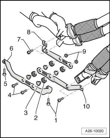
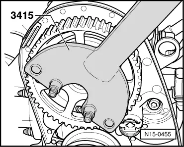
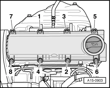
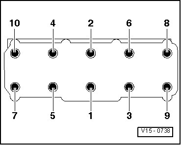
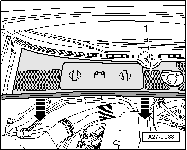
–  Remove cylinder head bolts in the sequence: -1 ... 10-.
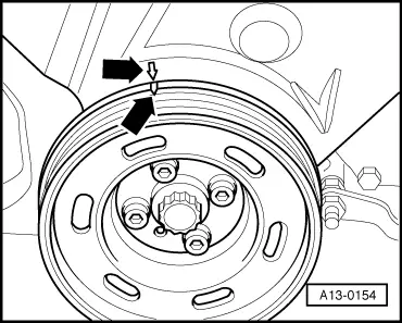
  Note
Use special wrench, long reach -T10070- to remove cylinder head bolts.
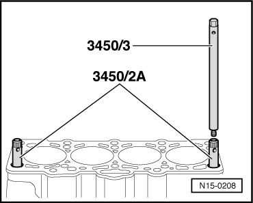
–  Remove the cylinder head with the assistance of a 2nd mechanic.
Installing
  Note
t  Renew the cylinder head bolts.
t  Renew self-locking nuts and bolts when performing assembly work.
t  Renew bolts which are tightened to a specified angle as well as oil seals and gaskets.
t  If repairing, carefully remove any remaining gasket material from the cylinder head and cylinder block. Ensure that no long scores or scratches are made on the surfaces.
t  Carefully remove any remaining emery and abrasive material.
t  No oil or coolant must be allowed to remain in the blind holes for the cylinder head bolts in the cylinder block.
t  Do not remove new cylinder head gasket from packaging until it is ready to be fitted.
t  Handle gasket very carefully. Damage to the silicone coating or the indented area will lead to leaks.
t  Cylinder heads which have cracks between the valve seats or between a valve seat insert and the spark plug thread can be re-installed without reducing service life, provided the cracks are only slight and do not exceed a maximum of 0.3 mm in width, and no more than the first 4 turns of the spark plug threads are cracked.
t  When installing an exchange cylinder head with fitted camshaft, the contact surfaces between roller rocker fingers and cams must be oiled after installing the head.
t  The plastic protectors fitted to protect the open valves should not be removed until the cylinder head is ready to be fitted.
t  
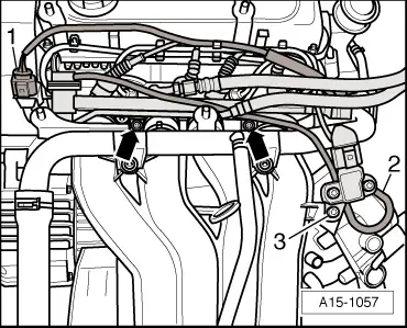
Secure all hose connections with the correct type of hose clips (same as original equipment) → Parts catalogue.
t  Fit all heat insulation sleeves in the original position when installing.
t  Fit all cable ties in the original positions when installing.
t  After working on the valve gear, turn the engine carefully at least 2 rotations by hand to ensure that none of the valves make contact when the starter is operated.
t  When fitting a new cylinder head or cylinder head gasket, drain off all the old coolant and refill with new coolant.
  N15-0026
–  Align mark on camshaft sprocket with mark on toothed belt cover -arrows-.
  A13-0691
–  Check again whether the crankshaft is positioned at “TDC”-arrows-.
  A13-0154
–  To centralize cylinder head gasket and cylinder head, screw guide pins -3450/2 A- into the outer bores on the intake side using fitting tool -3450/3-.
  Note
t  The maximum permissible diameter for the centering bores (outer holes on the intake side) in the cylinder head was restricted in the upper section.
t  Check before tightening whether the guide pins can be pushed through the bores in the cylinder head. If necessary, grind down the knurled surface of the guide pins slightly.
–  Fit new cylinder head gasket.
l  Check installation position of cylinder head gasket. Part number points towards cylinder head, and must be legible from the inlet side.
  Note
Two mechanics are needed to install the cylinder head.
–  Fit cylinder head onto cylinder block.
–  Insert 8 cylinder head bolts and tighten finger-tight.
–  Unscrew guide pins through bolt holes in cylinder head using fitting tool -3450/3- and install remaining cylinder head bolts.
  N15-0208
–  Tighten cylinder head bolts in three stages in the sequence shown:
1.  Tighten with torque wrench to 40 Nm.
2.  Turn 90° (1/4 turn) further using a rigid wrench.
3.  Turn 90° (1/4 turn) further using a rigid wrench.
  Note
Cylinder head bolts do not have to be torqued down again later after repair work.
  V15-0738
–  Install toothed belt cover (rear) -arrows-.
–  Insert parallel key into camshaft.
  Caution
If a piston is at TDC the valves could strike the piston when turning the camshaft. Pistons must therefore not be at TDC This could otherwise result in damage to valves and pistons.
  A15-0906
–  Tighten camshaft sprocket using counterhold -3415-.
Remaining installation steps are carried out in reverse sequence; note the following:
–  Install cylinder head cover → Chapter.
–  Fit toothed belt (adjust valve timing) → Anchor.
–  Install poly V-belt → Chapter.
–  Install intake manifold (top section) → Chapter.
–  Install coolant pipe (top) → Chapter.
–  Install front exhaust pipe together with catalytic converter → Chapter.
–  Align exhaust system free of stress → Chapter.
–  Observe notes on procedures required after connecting battery → Rep. Gr.27.
–  Check oil level → Chapter.
  Note
If engine oil is contaminated, perform oil change.
–  Fill cooling system with fresh coolant → Anchor.
Tightening torques
  N15-0455
ComponentNm
Rear toothed belt cover to cylinder headM610 1)
M823 1)
Camshaft sprocket to camshaft100
Connecting pipe to exhaust gas recirculation valve -N18-22
l  1) Install using locking fluid; locking fluid → Parts catalogue.


Removing and installing intake manifold > < Removing and installing cylinder head cover