audi Workshop Repair Guides

Audi Workshop Service and Repair Manuals

Removing and installing cylinder head cover > < Removing and installing cylinder head|Part II
4-Cylinder engine (5-valve), Mechanics
Removing and installing cylinder head
Removing and installing intake manifold

Removing

Note:

All cable ties which are released or cut open when removing must be fitted in the same position when installing.

  • ‒ Obtain radio code on vehicles with coded radio.
  • ‒ With ignition switched off disconnect battery earth strap.
 
A10-0259
  • ‒ → Disconnect hose -1- going to upper coolant pipe.
  • ‒ Unbolt coolant expansion tank -2- (-arrows-).
  • ‒ Disconnect wire for coolant shortage indicator switch -F66 and move coolant expansion tank to one side.

Note:

Do not disconnect coolant hose -3-.

Vehicles with cruise control system

  • ‒ Disengage actuatorrod at throttle valve control part.
 
A15-0203
  • ‒ Pull vacuum hose offvacuum unit.

All models

  • ‒ → Disconnect air intake hose at intake pipe connection and air mass meter -arrows-.

 
A10-0242
  • ‒ → Remove cover over injectors -arrows on right-.
 
A10-0289
  • ‒ → Detach throttle cable at the throttle valve control part and at support bracket (do not remove throttle cable retainer). Move throttle cable clear to the side.
  • ‒ Disconnect vacuum hose -2- for ACF valve.
  • ‒ Disconnect vacuum hose -1- for brake servo.

 
A15-0245
  • ‒ → Unplug connector -1- at throttle valve control part -J338.
  • ‒ Move wiring clear.

Vehiclesä 07.97:

  • ‒ Unplug connector -2- at intake air temperature sender -G42.

Vehicles08.97 ä:

 
A15-0208
  • ‒ → Disconnect wires/unplug connectors as follows:
  •     1 -    intake air temperature sender -G42
  •     2 -    Intake manifold change-over valve -N156

All models

 
A10-0302
  • ‒ → Remove intake air pipe -arrows-.

Note:

Detach hoses under intake air pipe after removing pipe.

 
A15-0201
  • ‒ → Fit hose clamps 3094 on coolant hoses going to throttle valve control part.
  • ‒ Disconnect coolant hoses from throttle valve control part.

Note:

Throttle valve control part is shown in illustration with engine removed.

 
A15-0128
  • ‒ → Pull connector off Hall sender -G40 -arrow-.
 
A15-0204
  • ‒ → Unscrew retaining bolts for fuel distributor railand disconnect vacuum line from fuel pressure regulator -arrows-.
  • ‒ Pull fuel distributor rail together with injectors off intake manifold and place it on a clean cloth at the back of the engine compartment.

 
A15-0205
  • ‒ → Unbolt intake manifold from the two bottom supports -arrows-.
 
A15-0202
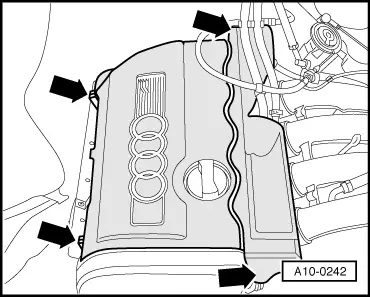
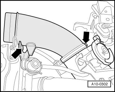
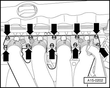
  • ‒ → Unbolt intake manifold from cylinder head -arrows- and remove.

Note:

Plug intake ports on cylinder head with clean cloths.

Installing

Installation is carried out in the reverse order, when doing this note the following:

Note:

Replace gaskets and seals.

  • ‒ Adjust throttle cable
  • ‒ Fill cooling system => Page 19-7
  • ‒ After connecting battery, enter anti-theft code for radio

=> Radio operating instructions

  • ‒ Close windows fully using electric window switches.
  • ‒ Then operate all electric window switches again for at least one second in the "close" direction to activate the automatic one-touch function.
  • ‒ Set clock to correct time.
  • ‒ Perform adaption of throttle valve control part:

=> Motronic injection and ignition system (4-cylinder); Repair Group 24; Checking throttle valve control part -J338; Performing basic setting of throttle valve control part -J338

=> Motronic injection and ignition system (4-cylinder)07.96 ä; Repair group 24; Testing throttle valve control part; Performing adaptation of throttle valve control part

Tightening torques

Component

Nm

Intake manifold to cylinder head

10

Intake manifold support

to intake manifold

20

to bracket

20

to sump

20

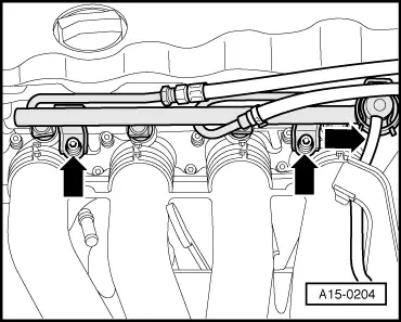
Fuel distributor rail to intake manifold

10

Removing and installing cylinder head cover > < Removing and installing cylinder head|Part II