- Metal/rubber gasket
- Gasket
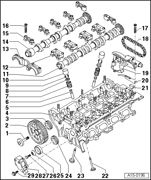
- Exhaust valve
-
◆ With sodium filling
-
◆ Note instructions on scrapping valves with a sodium filling => Page 15-43
-
◆ Do not rework, only grinding-in is permitted
-
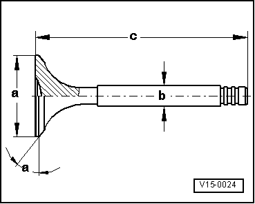
◆ Valve dimensions => Fig. 1
-
◆ Checking valve guides, grinding in valve seats => Page 15-73
- Inlet valve
-
◆ Do not rework, only grinding-in is permitted
-
◆ Valve dimensions => Fig. 1
-
◆ Checking valve guides, grinding in valve seats => Page 15-73
|