
A4 Mk1
 |
|
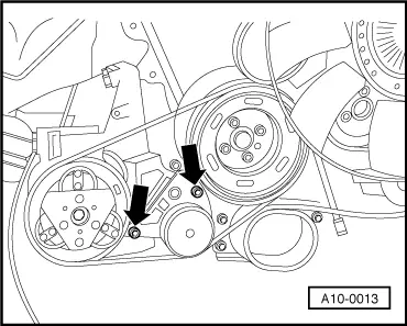
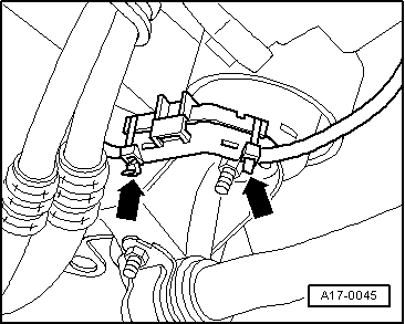
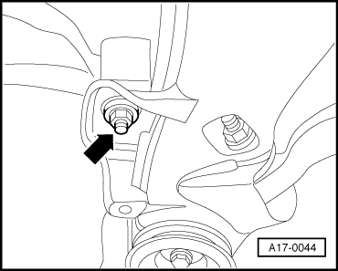
Vehicles with air conditioner: |
 |
|
|
Note: Mark the direction of rotation with chalk or felt pen before removing the ribbed belt. If the belt rotates in the wrong direction when it is refitted, it may break.
All models |
 |
|
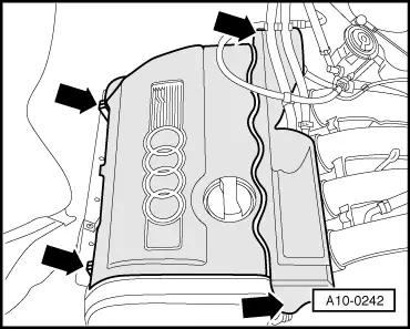
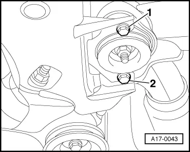
Note: Illustration shows vehicle with air conditioner. Vehicles with air conditioner: |
 |
|
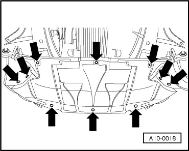
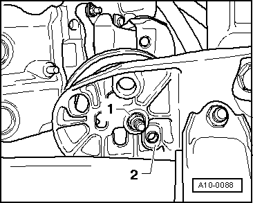
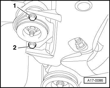
Note: Shown in illustration with engine removed. All models |
 |
|
|
 |
|
|
 |
|
|
 |
|
|
 |
|
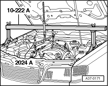
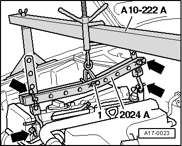
Important
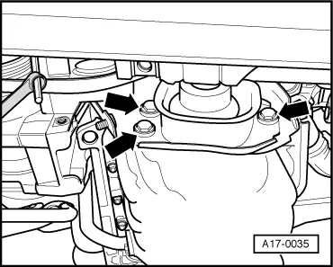
The hooks and locating pins of the lifting tackle must be secured with locking pins -arrows in illustration-.
Note: |
 |
|
|
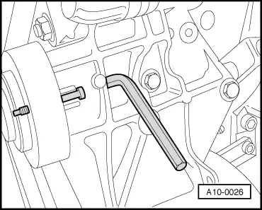
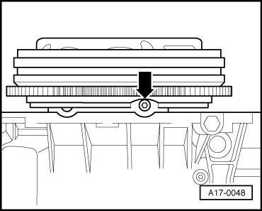
Do not lift engine so far that coolant hoses, pipes or wiring are damaged or stretched. Ensure adequate clearance for viscous fan. If necessary, remove viscous fan as follows.
|
 |
|
|
 |
|
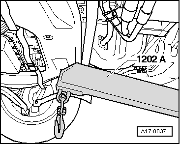
Note: The subframe should be detached and lowered only at the front, otherwise it will be necessary to check wheel alignment. |
|
|
Vehicles with manual gearbox |
 |
|
Vehicles with automatic gearbox |
 |
|
All models |
 |
|
|
 |
||||||||||||||||||||||||||||||||||
|
Notes:
Installing Installation is carried out in the reverse order, when doing this note the following: Notes:
Tightening torques
| ||||||||||||||||||||||||||||||||||