
A4 Mk1
| Removing engine |

| Special tools and workshop equipment required |
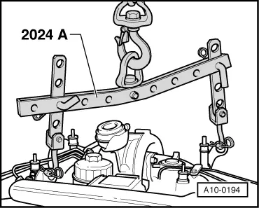
| t | Lifting tackle -2024 A- |
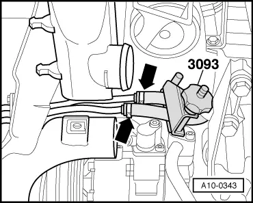
| t | Hose clamps for hoses up to 40 mm -3093- |
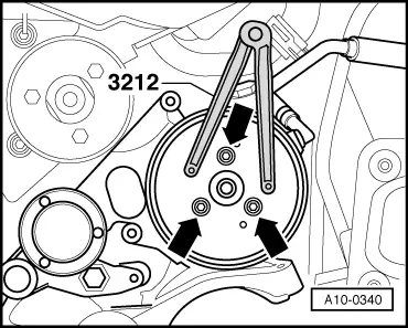
| t | Pin wrench -3212- |
| t | Open-end spanner -3312- |
| t | Hose clip pliers -V.A.G 1921- |
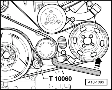
| t | Locking pin -T10060 A- |

| t | Used oil collection and extraction unit -V.A.G 1782- |
| t | Workshop hoist -VAS 6100- |
| t | Drip tray for workshop hoist -VAS 6208- |
| t | Special tool -V/175- for vehicles with automatic gearbox |
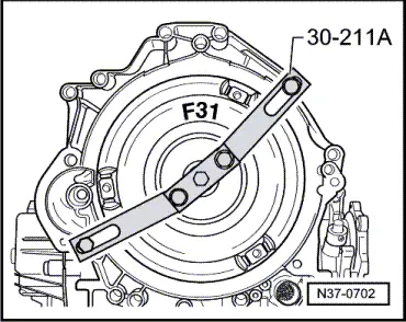
| t | Support bridge -30 - 211 A- for vehicles with automatic gearbox |
 Note
Note
|
|
|
|
|
 Caution
 WARNING
|
|
|
|
|
|
|
|
|
|
|
|
|
|
|
|
|
|
|
|
Note
|
|
|
|
|
|
|
|
|
|
|
|
|
|
|
|
|
|
|
|
|
|
|
|
|
|
|
|
|
|
|
|
|
|
|
|
|
|
|
|
|
|
|
|
|
|
|
|
Note
|
|
|
|
|
|
|
|
|
|
|
|
Note
|
|
|
|
Note
|
|
|
|
|
|
Note
|
|
Note
|
|
Note
|
|
Note
Note
Note
|
|
|
|
|
|