audi Workshop Repair Guides

Audi Workshop Service and Repair Manuals

Installing cylinder head > < Removing cylinder head (left-side)
Removing cylinder head (right-side)
Special tools and workshop equipment required
   
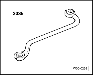
t  Ring spanner -3035-
Removing
l  Engine in vehicle.
l  Lock carrier must be in service position → Chapter.
  Note
Fit all cable ties in the original positions when installing.
  Caution
To prevent damage to the electronic components when disconnecting the battery:
Observe notes on procedure for disconnecting the battery.
–  Disconnect earth cable at battery → Rep. Gr.27.
–  Drain coolant → Chapter.
–  Remove right exhaust manifold together with intermediate pipe → Chapter.
–  Take toothed belt off camshaft sprockets → Chapter.
–  Remove intake manifold (front section) → Chapter.
  W00-0269
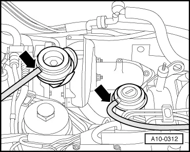
–  Disconnect vacuum hoses -arrows- from turbocharger and mechanical exhaust gas recirculation valve.
  A10-0312
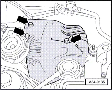
–  Remove heat shield above turbocharger -arrows-.
–  Mark injector pipes according to cylinder (e.g. with felt-tip pen).
–  Disconnect injector pipes one by one with ring spanner -3035-.
  A34-0135
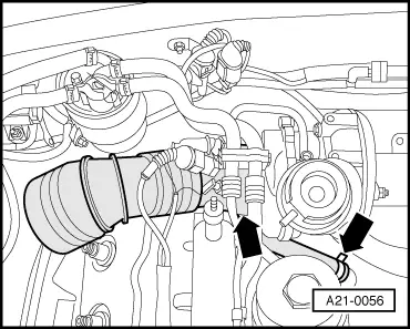
–  Remove air intake hose -arrows-.
  A21-0056
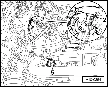
–  Unplug electrical connectors -1 ... 3-.
–  Unplug electrical connector -4- at injection pump.
–  Unplug electrical connector -5- for coolant temperature sender.
–  Unplug electrical connectors on glow plugs.
–  Move wiring harness clear.
  A10-0284
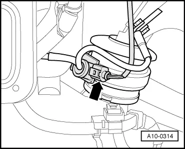
–  Unplug electrical connector -arrow- at engine mounting (right-side).
–  Move wiring harness clear.
  A10-0314
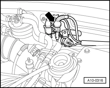
–  Unplug electrical connector -arrow- and move wiring for needle lift sender clear.
  A10-0316
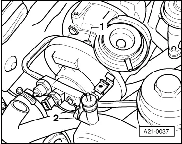
–  Detach oil pipe -1- at turbocharger.
–  Unscrew oil pipe at intake manifold -2-.
  A21-0037
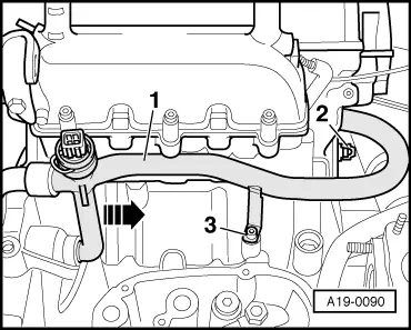
–  Remove bolts -2- and -3-.
–  Press coolant pipe -1- towards rear of vehicle and leave in position.
  Note
Illustration shows coolant pipe with oil filter bracket removed.
  A19-0090
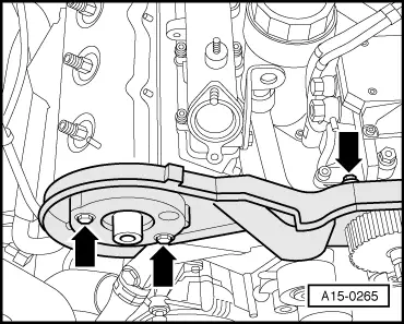
–  Remove toothed belt cover (rear right) -arrows-.
–  Unscrew guide tube for dipstick at cylinder head and lift off.
  A15-0265
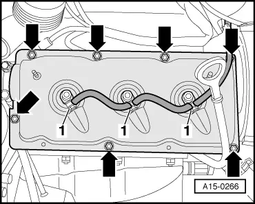
–  Disconnect return pipe from injectors -1-.
–  Unscrew nuts -arrows- for cylinder head cover and detach cylinder head cover.
  A15-0266
–  Slacken cylinder head bolts in the sequence indicated and remove bolts.
–  Take off cylinder head and place it on a soft surface (such as foam plastic).
  Caution
Risk of damage to injectors and glow plugs when putting down cylinder head.
After removal, the cylinder head must not be put down on the gasket side with the injectors and the glow plugs still installed, because the glow plugs project slightly beyond the gasket surface.
  A15-0186

Installing cylinder head > < Removing cylinder head (left-side)