
A4 Mk1
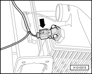
| Checking intake manifold pressure sender -G71- |

| Special tools and workshop equipment required |
| t | Hand-held multimeter -V.A.G 1526D- |
| t | Auxiliary measuring set -V.A.G 1594C- |
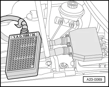
| t | Adapter -V.A.G 1598/30- (engine code AFB for vehicles with manual gearbox or automatic gearbox; engine code AKN for vehicles with manual gearbox) |
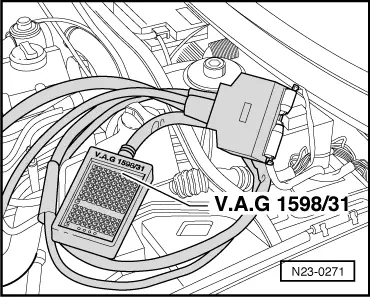
| t | Adapter cable, 121-pin -V.A.G 1598/31- (engine code AKN for vehicles with automatic gearbox) |
| t | Vehicle diagnostic, testing and information system -VAS 5051B- |
 Note
Note
|
|
|
|
|
|
|
|
|
|
|
|
|
|
 Caution
|
|
|
|
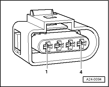
| Connector Contact | -V.A.G 1598/30- Socket | -V.A.G 1598/31- Socket |
| 1 | 3/16 | 52 |
| 3 | 3/14 | 31 |
| 4 | 3/15 | 71 |
|