audi Workshop Repair Guides

Audi Workshop Service and Repair Manuals

Checking camshaft axial clearance > < Testing solenoid valves for camshaft timing control
6-Cylinder engine (5-valve turbo), Mechanics
Servicing valve gear
Removing and installing camshafts and camshaft adjusters

Removing

  • ● Cylinder head installed
 
A10-0018
  • ‒ → Remove noise insulation panel -arrows-.
  • ‒ Remove front bumper

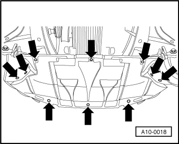
=> General body repairs; Repair group 63; Front bumper; Removing and installing front bumper

  • ‒ Move lock carrier to service position

=> General body repairs; Repair Group 50; Removing and installing lock carrier; Service position of lock carrier

  • ‒ Remove ribbed belt .
  • ‒ Remove toothed belt => Page 13-5.

Left cylinder head:

  • ‒ Remove left-hand cylinder head cover

Right cylinder head

  • ‒ Remove right-hand cylinder head cover

All:

  • ‒ Unbolt Hall sender housing (10 Nm).
  • ‒ Remove bolt securing Hall sender rotor (20 Nm) and carefully lever off rotor using a screwdriver.
  • ‒ Insert camshaft clamp 3391 in the securing plates of the two camshafts.
  • ‒ Loosen both camshaft bolts and unscrew approx. 5 turns.
  • ‒ Take out camshaft clamp 3391.
 
A13-0163
  • ‒ → Pull off both camshaft sprockets with special tool T40001.
  • ‒ Using a screwdriver, carefully lever oil feed pipes for camshaft bearings out of camshaft bearings.

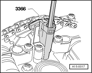
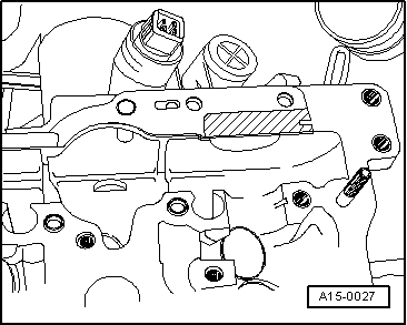
Make sure that the retaining catches do not break off when levering out the oil pipes.

 
A15-0017
  • ‒ → Secure camshaft adjuster using retainer for chain tensioner 3366.

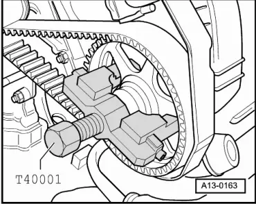
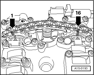
Note:

Do not overtighten retainer for chain tensioner, otherwise camshaft adjuster can be damaged.

 
A15-0213
  • ‒ → Check TDC position of camshafts once again.

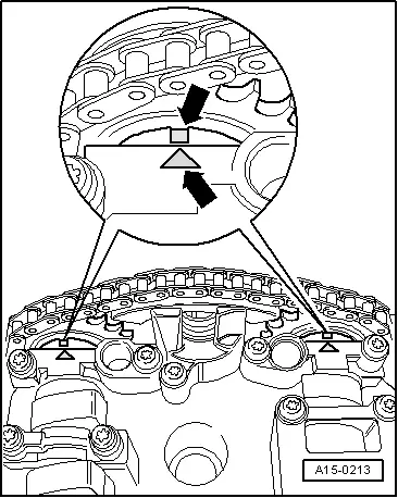
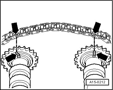
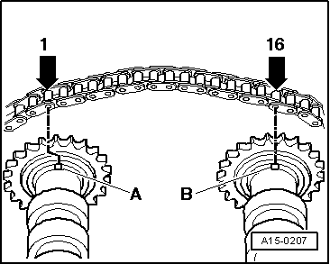
Note:

The two markings on the camshafts must be in line with the two arrows on the bearing caps.

  • ‒ Clean drive chain and camshaft chain sprockets in the vicinity of the arrows on the bearing caps and mark the position of the chain on the sprockets with paint opposite the two arrows.

 
A15-0193

Notes:

  • ◆ → The distance between the two arrows (and thus between the paint markings) is 16 rollers on the chain.
  • ◆ The notch on the exhaust camshaft is offset slightly towards the inside in relation to chain roller -1-.
  • ◆ Do not mark the chain with a centre punch or by making a notch or similar.
 
A15-0098
  • ‒ → Unscrew bolts securing camshaft adjuster -6-.
  • ‒ Remove bearing caps 1, 3, 5 and 7 from inlet and exhaust camshafts and place them in the correct order on a clean surface.
  • ‒ Slacken off bearing caps 2 and 4 alternately and in diagonal sequence, and remove from both camshafts.
  • ‒ Take out both camshafts together with the camshaft adjuster.

Installing

 
A15-0027
  • ‒ → Renew rubber/metal gasket for camshaft adjuster and apply a thin coat of sealant "D 454 300 A2" to the shaded area.
 
A15-0212
  • ‒ Fit drive chain on camshaft sprockets as follows:
    • ‒ → When the old chain is being used again, fit the chain so that the paint parkings are in line.

 
A15-0207
    • ‒ → When a new chain is being installed, the distance between the notches -A- and -B- on the camshafts must be 16 rollers on the chain. The illustration shows the exact positions of the 1st and 16th rollers on the sprockets.
    • ‒ Notch -A- is offset slightly towards the inside in relation to chain roller -1-.
  • Insert the camshaft adjuster inside the chain (second mechanic required).
  • Locate camshafts with chain and camshaft adjuster in cylinder head.
  • Oil camshaft bearing surfaces.

Notes:

  • ◆ The dowel sleeves for the bearing caps and camshaft adjuster must be in the cylinder head.
  • ◆ Install the bearing caps so that the markings on the bearing caps can be read from the inlet side of the cylinder head.
 
A15-0090
  • ‒ Tighten bolts securing chain tensioner (watch position of dowel sleeves).
  • ‒ → Tighten bearing caps 2 and 4 of inlet and exhaust camshafts alternately and in diagonal sequence (watch position of dowel sleeves).
  • ‒ Fit the two bearing caps next to the chain sprockets on the inlet and exhaust camshafts.
 
A15-0213
  • ‒ Check correct setting of camshafts:
    • ‒ → The two markings on the camshafts must be in line with the two arrows on the bearing caps -arrows-.

 
A15-0193
    • ‒ → The distance between the two arrows on the bearing caps (or between the paint markings) is 16 rollers on the chain.
    • ‒ The notch on the exhaust camshaft is offset slightly towards the inside in relation to chain roller -1-.
 
A15-0098
  • ‒ → Prepare shaded areas on double bearing cap -1- and bearing
    cap -7- .....

 
A15-0084
  • ‒ → ... by applying a thin coat of sealant and install bearing caps (watch position of dowel sleeves).
  • ● Sealant

=> Parts catalogue

  • ‒ Install remaining bearing caps (watch position of dowel sleeves).
  • ‒ Fit new oil feed pipes for camshaft bearings.
  • ‒ Fit new oil seals for inlet and exhaust camshafts;
    installing => Page 15-9.
  • ‒ Remove retainer for chain tensioner 3366.

Notes:

  • ◆ When new tappets have been installed the engine must not be started for about 30 minutes. The hydraulic compensation elements must settle (otherwise valves will strike pistons). Then turn crankshaft two full revolutions before starting.
  • ◆ After working on the valve gear, turn over the engine carefully at least two revolutions by hand to ensure that none of the valves make contact when the starter is operated.

 
A15-0097
  • ‒ → Seal end points of joints between bearing caps and cylinder head.
  • ‒ Before installing cylinder head cover and gasket, carefully apply a small quantity of sealant at the four end points of the sealing surfaces on the cylinder head -arrows-, using a small screwdriver.
  • ◆ Sealant

=> Parts Catalogue

  • ‒ Install cylinder head covers => Page 15-21.
  • ‒ Install toothed belt => Page 13-5.
  • ‒ Install ribbed belt => Page 13-1.

Tightening torques

Component

Nm

Bolts

M6

10

M8

20

Except for the following:

Bearing caps to cylinder head

10

Camshaft adjuster to cylinder head

10

Hall sender rotor to camshaft

25

Hall sender housing to cylinder head

10

Camshaft sprocket to camshaft

55

Cylinder head cover

10

Checking camshaft axial clearance > < Testing solenoid valves for camshaft timing control