
A4 Mk1
 |
|
|
 |
|
|
 |
|
|
 |
|
|
 |
|
|
 |
|
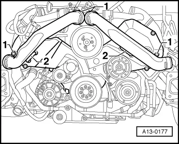
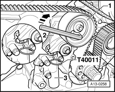
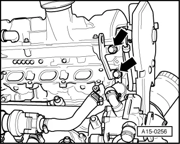
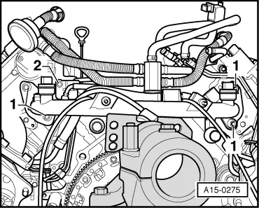
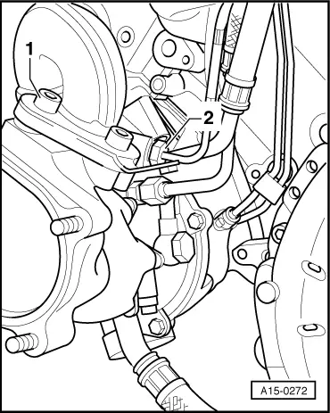
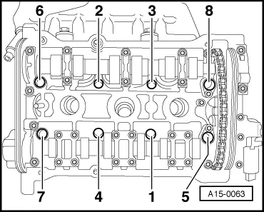
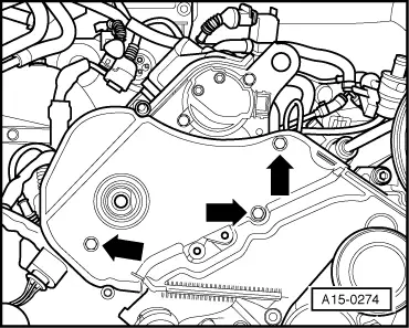
Note: Watch position of retaining strips -2-. |
 |
|
|
 |
|
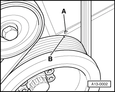
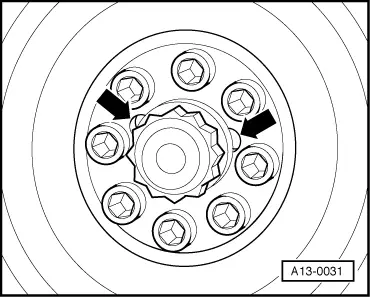
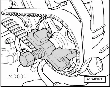
Note: Turn over the engine at the central bolt on the crankshaft.
|
 |
|
|
 |
|
Note: The central bolt does not have to be loosened to remove the vibration damper. |
 |
|
Notes: |
 |
|
|
 |
|
|
 |
|
|
 |
|
|
 |
|
|
 |
|
|
 |
|
|
 |
|
|
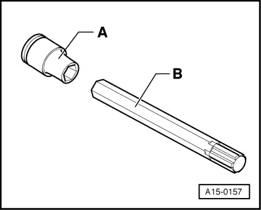
Note: → Use special tool 3452 together with a normal commercial 10 mm socket when removing and installing. Installing Notes:
When installing a new cylinder head:
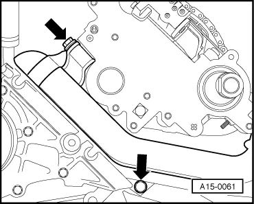
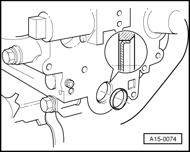
The cylinder head supplied as a replacement part can be used on both sides (left or right). But a sealing cap (core plug) must be fitted in the front end of the cylinder head in each case. |
 |
|
=> Parts Catalogue
|
 |
|
It is not necessary to torque down cylinder head bolts again after repairs have been completed. |
 |
|||||||||||||||||||||||||||||||||
=> Parts Catalogue Tightening torques
Removing and installing right cylinder head Notes:
Removing
| |||||||||||||||||||||||||||||||||
|
|
|
 |
|
|
 |
|
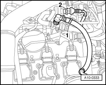
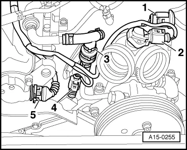
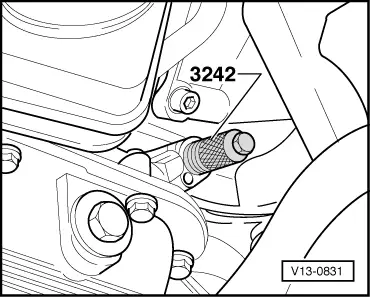
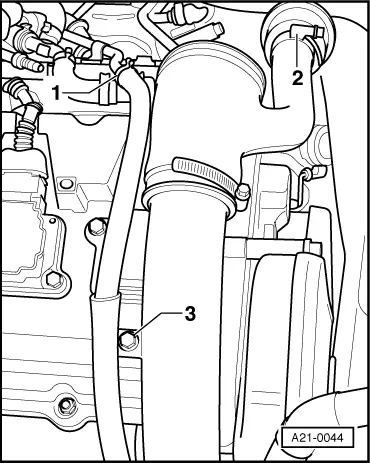
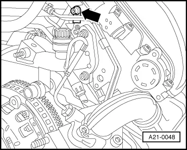
Note: Insert plug in lower section of intake pipe. |
|
|
|
|
|
|
|
|
|
|
|
|
|
|
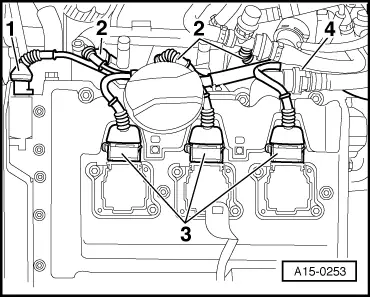
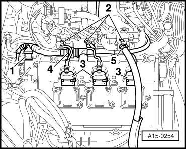
Note: Watch position of retaining strips -2-. |
|
|
|
|
|
Note: Turn over the engine at the central bolt on the crankshaft.
|
|
|
|
|
|
Note: The central bolt does not have to be loosened to remove the vibration damper. |
|
|
Notes: |
|
|
|
|
|
|
 |
|
|
|
|
|
 |
|
|
 |
|
|
|
|
|
Note: → Use special tool 3452 together with a normal commercial 10 mm socket when removing and installing. Installing Notes:
When installing a new cylinder head:
The cylinder head supplied as a replacement part can be used on both sides (left or right). But a sealing cap (core plug) must be fitted in the front end of the cylinder head in each case. |
|
|
=> Parts Catalogue
|
|
|
It is not necessary to torque down cylinder head bolts again after repairs have been completed. |
|
||||||||||||||||||||||||||||||||||
=> Parts Catalogue Tightening torques
| ||||||||||||||||||||||||||||||||||