audi Workshop Repair Guides

Audi Workshop Service and Repair Manuals

Removing and installing camshafts and camshaft adjusters > < Checking function of camshaft timing control
6-Cylinder engine (5-valve turbo), Mechanics
Servicing valve gear
Testing solenoid valves for camshaft timing control
 
G24-0023

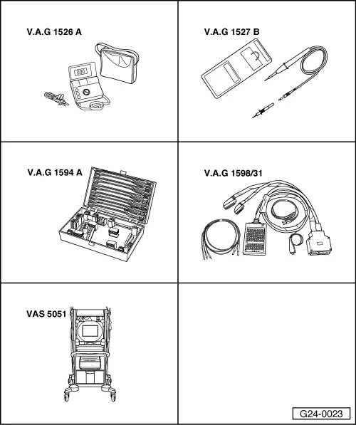
Special tools and workshop equipment required

  • ◆ V.A.G 1526 A
  • ◆ V.A.G 1527 B
  • ◆ V.A.G 1594 A
  • ◆ V.A.G 1598/31
  • ◆ VAS 5051
  • or
  • ◆ V.A.G 1551 with V.A.G 1551/3 A
  • ‒ Start final control diagnosis and select solenoid valves for camshaft adjustment.

=> Motronic injection and ignition system; Repair group 01; Final control diagnosis

 
A34-0163

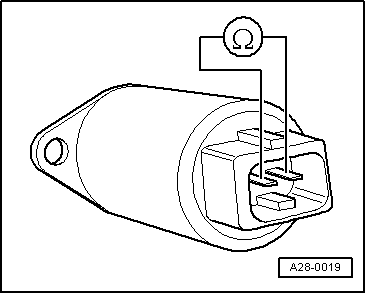
If one of the valves is not activated (does not click) during final control diagnosis:

Testing internal resistance

  • ‒ Switch off ignition.
  • ‒ → Unscrew bolts -arrows- and remove engine cover panels -A...C-.

 
A24-0150
  • ‒ → Remove air duct -arrows-.
 
A28-0019
  • ‒ Unplug electrical connector on relevant solenoid valve.
  • ‒ → Connect multimeter to valve (resistance measurement range)
    • ‒ Specification: 10 ... 18ω

If the specification is not obtained:

  • ‒ Fit a new valve.

Checking voltage supply

 
V96-0749
  • ‒ Unplug connector on relevant valve.
  • ‒ → Connect voltage tester V.A.G 1527 B as follows:

Connector
Contact

Measure against

1

Engine earth

  • ‒ Operate starter briefly.
    • ‒ The LED should light up.

If the LED does not light up:

  • ‒ Carry out the following tests (marked with dots):
  • ● Check fuse for solenoid valves for camshaft timing control.

=> Current flow diagrams, Electrical fault-finding and Fitting locations

 
V96-0749
  • ● → Test for open circuit in wiring from fuel pump relay to connector contact 1 via fuse -S234 (socket 34 in fuse box):

=> Current flow diagrams, Electrical fault finding and Fitting locations

  • ‒ Rectify any open circuits.

If no fault is found:

  • ‒ Test fuel pump relay.

=> Motronic ignition and injection system; Repair group 24; Servicing Motronic injection system; Testing fuel pump relay and activation.

Testing activation

 
V96-0749
  • ‒ → Connect voltage tester V.A.G 1527 B between contacts 1 (positive) and 2 using test cables from V.A.G 1594 A.
  • ‒ Start final control diagnosis and activate solenoid valves for camshaft timing control.

=> Motronic injection and ignition system; Repair group 01; Final control diagnosis

    • ‒ The LED should flash.

If the LED lamp does not flash or if it lights up continuously:

  • ‒ Connect test box V.A.G 1598/31 to wiring harness for engine control unit.Do notconnect to the engine control unit itself.

=> Motronic injection and ignition system; Repair group 24; Servicing Motronic injection system; Testing fuel pump relay and activation

 
V96-0749
  • ‒ → Test for open circuit and short to positive or earth in the following wiring connections:

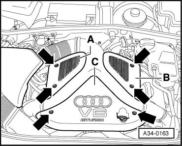
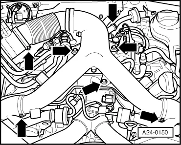
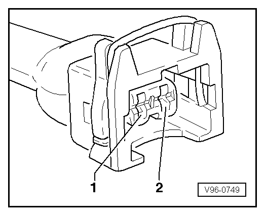
Inlet camshaft timing adjustment valve -1- -N205 and inlet camshaft timing adjustment valve -2- -N208

Connector
Contact

Test box V.A.G 1598/31
Socket

2

=> Current flow diagrams, Electrical fault-finding and Fitting locations

  • ‒ Eliminate open circuit or short circuit to earth if necessary.

If the wiring is OK:

  • ‒ Fit a new engine control unit

=> Motronic injection and ignition system; Repair group 24; Servicing Motronic injection and ignition system; Renewing engine control unit

If no fault is found:

  • ‒ Install a new mechanical camshaft adjuster.

Removing and installing camshafts and camshaft adjusters > < Checking function of camshaft timing control