audi Workshop Repair Guides

Audi Workshop Service and Repair Manuals

Testing function of exhaust gas temperature senders (display groups 112 and 220/221) - vehicles with engine code AZB only > < Exhaust gas temperature control
6-Cylinder engine (5-valve turbo), Mechanics
Exhaust gas temperature control
Testing function of exhaust gas temperature senders (display groups 200/201 and 202) - vehicles with engine code AGB only
 
W00-0706

Special tools and workshop equipment required

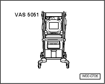
  • ◆ VAS 5051 with VAS 5051/1
  • or
  • ◆ V.A.G 1551 and V.A.G 1551/3 A

Test requirement:

  • ● Coolant temperature at least 80 °C
Warning
  • ◆ Test equipment must always be secured on the rear seat and operated from the rear seat by a second person.
  • ◆ If test equipment is operated from the front passenger seat, the occupant could be injured by the passenger's airbag in an accident.

Test sequence

  • ‒ Connect vehicle diagnostic, testing and information system VAS 5051 (or fault reader V.A.G 1551) and select engine electronics control unit by entering address word "01".
    When doing this the engine must be idling.

=> Motronic injection and ignition system; Repair group 01; Self-diagnosis of Motronic; Connecting vehicle diagnostic, testing and information system VAS 5051 or fault reader V.A.G 1551 and selecting functions.

 
→ Indicated on display:
Rapid data transfer     HELP
Select function XX
  • ‒ Enter "08" to select the function "Read measured value block" and confirm entry with Q key.
 
→ Indicated on display:
Read measured value block    Q
Enter display group number XXX
  • ‒ Enter "202" to select Display Group 202 and confirm entry with Q key.
 
→ Indicated on display:
(1...4=Display zones)
Read measured value block 202    ⇒
    1    2    3    4
  • ‒ Test the exhaust gas temperature control
  • ‒ Perform a road test during which
    • ‒ Full throttle at engine speeds between 5000...6500 rpm
  • is attained.

Display zones

1

2

3

4

Display group 202: Exhaust gas temperature

Display

xxxx rpm

%

%

%

Indicates

Engine speed

Load

Enrichment factor sensor Bank 1

Enrichment factor sensor Bank 2

Specification

>5000

> 100

0....30 1)

0....30 1)

Note

Display min: 15
Display max: 175

A fault will be registered in the memory if the enrichment factor exceeds 30 %

A fault will be registered in the memory if the enrichment factor exceeds 30 %

1)    The control unit recognizes a fault if the difference between bank 1 and bank 2 is more than 8.5 % for a period of 5 sec. and enriches both banks by 30%.

If values above 20% are displayed continuously, then possible causes could be:

  • ◆ Fuel pressure too low.
  • ◆ Air mass meter signal too low.
  • ‒ Proceed to measured value block 220.
 
→ Indicated on display:
(1...4=Display zones)
Read measured value block 200    ⇒
    1    2    3    4
  • ‒ Test exhaust gas temperature control.

Note:

The exhaust gas temperature should increase to 980°C (display 42 %) to initiate the control process. Values below945°Care displayed as 5%.

Display zones

1

2

3

4

Display group 200: Exhaust gas temperature control

Display

xxxx rpm

%

%

Text

Indicates

Engine speed

Load

On-off ratio sensor Bank 1

Operating status Bank 1

Specification

> 5000

> 100

42 ± 10

Control ON

Note

Increase engine speed and load until control switches to "ON"

Display min: 5
Display max: 95

  • ‒ Repeat test procedure for Bank 2=>Measured value block 201.

Display zones

1

2

3

4

Display group 201: Exhaust gas temperature control

Display

xxxx rpm

%

%

Text

Indicates

Engine speed

Load

On-off ratio sensor Bank 2

Operating status Bank 2

Specification

> 5000

> 100

42 ± 10

Control ON

Note

Increase engine speed and load until control switches to "ON"

Display min: 5
Display max: 95

If the specifications are not obtained and a fault is stored in the fault memory:

  • ‒ Check exhaust gas temperature sender.

Testing function of exhaust gas temperature senders (display groups 112 and 220/221) - vehicles with engine code AZB only > < Exhaust gas temperature control