audi Workshop Repair Guides

Audi Workshop Service and Repair Manuals

Testing charge pressure sender -G31 > < Testing charge pressure control
6-Cylinder engine (5-valve turbo), Mechanics
Charge air system with turbocharger
Testing air recirculation valve for turbocharger -N249
 
G24-0021

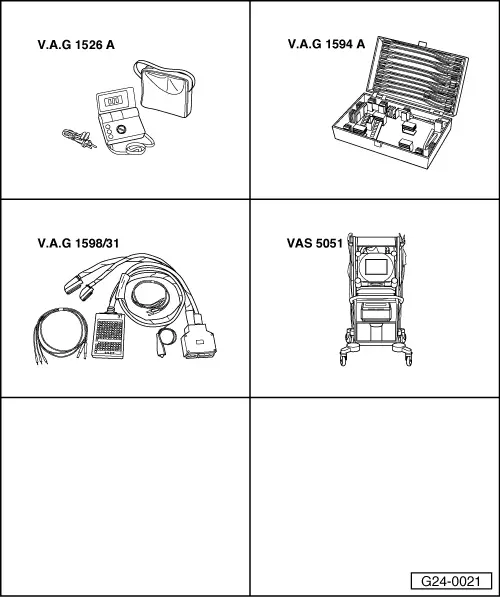
Special tools and workshop equipment required

  • ◆ V.A.G 1526 A
  • ◆ V.A.G 1527 B
  • ◆ V.A.G 1594 A
  • ◆ V.A.G 1598/31
  • ◆ VAS 5051 with VAS 5051/1
  • or
  • ◆ V.A.G 1551 with V.A.G 1551/3 A

Note:

The air recirculation valve for turbocharger -N249 and its wiring are monitored by the engine control unit.

  • ‒ Connect vehicle diagnostic, testing and information system VAS 5051 (or fault reader V.A.G 1551) and select engine electronics control unit by entering address word "01"
    When doing this the engine must be idling.

=> Motronic injection and ignition system; Repair group 01; Self-diagnosis of Motronic; Connecting vehicle diagnostic, testing and information system VAS 5051 or fault reader V.A.G 1551 and selecting functions

  • ‒ Interrogate fault memory of engine control unit.

=> Motronic injection and ignition system; Repair group 01; Interrogating and erasing fault memory

If the display shows a fault relating to air recirculation valve for turbocharger -N249:

  • ‒ Disconnect hoses from air recirculation valve; the electrical connector remains connected.
  • ‒ Connect auxiliary hose to valve at one of the connections.
  • ‒ Start final control diagnosis and select air recirculation valve for turbocharger -N249.

=> Motronic injection and ignition system; Repair group 01; Final control diagnosis

 
→ Indicated on display:
Final control diagnosis    ⇒
Air recirc. valve for turbocharger -N249

The valve should click ...

... and open and close (can be checked by blowing into auxiliary hose).

If the valve does not click:

  • ‒ Test internal resistance of valve.

If the valve does not open and close properly:

  • ‒ Renew air recirculation valve for turbocharger -N249.

Testing internal resistance

  • ‒ Unplug electrical connector from valve.
 
A24-0077
  • ‒ → Connect multimeter to valve (resistance measurement range)
    • ‒ Specification: 27 ... 30ω

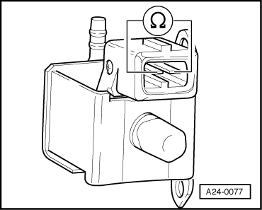
If the specification is not obtained:

  • ‒ Renew air recirculation valve for turbocharger -N249.

If the specification is obtained:

  • ‒ Check voltage supply.

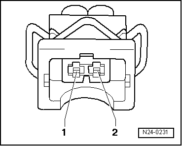
Checking voltage supply

Note:

The air recirculation valve receives its voltage supply via the fuel pump relay.

Test requirement:

  • ● Fuse for air recirculation valve OK.
  • ‒ Disconnect electrical connector from valve.
 
A24-0231
  • ‒ → Connect voltage tester V.A.G 1527 B as follows:

Connector
Contact

Measure against

1

Engine earth

  • ‒ Operate starter briefly.
    • ‒ The LED should light up.

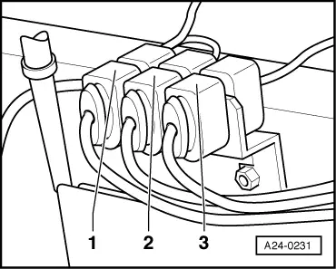
If the LED does not light up:

  • ‒ Test for open circuit in wiring connection between fuel pump relay and contact 1 on connector via fuse

=> Current flow diagrams, Electrical fault finding and Fitting locations

  • ‒ Rectify any open circuits.

If the wiring is OK:

  • ‒ Test fuel pump relay.

=> Motronic injection and ignition system; Repair group 24; Servicing Motronic injection system; Checking fuel pump relay and activation.

If the LED lights up:

  • ‒ Check activation.

Checking activation

 
A24-0231
  • ‒ → Connect voltage tester V.A.G 1527 B to contact 1 (positive) and contact 2 of the connector.
  • ‒ Start final control diagnosis and select air recirculation valve for turbocharger -N249.

=> Motronic injection and ignition system; Repair group 01; Final control diagnosis

    • ‒ The LED should flash.

If the LED lamp does not flash or if it lights up continuously:

  • ‒ Connect test box V.A.G 1598/31 to wiring harness for engine control unit.Do notconnect to the engine control unit itself.

=> Motronic injection and ignition system; Repair group 24; Servicing Motronic injection system; Checking fuel pump relay and activation.

 
N24-0231
  • ‒ → Test for open circuit and short to positive or earth in the following wiring connections:

Connector
Contact

Test box V.A.G 1598/31
Socket

2

9

  • ‒ Rectify any open/short circuit as necessary.

If the wiring is OK:

  • ‒ Fit a new engine control unit.

=> Motronic injection and ignition system; Repair group 24; Servicing Motronic injection system; Renewing engine control unit

Testing charge pressure sender -G31 > < Testing charge pressure control