
A4 Mk1
|
Charge air system with turbocharger
Testing charge pressure control
|
 |
|
|
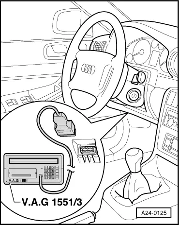
Special tools and workshop equipment required
Test requirement:
Warning
|
 |
|
|
Test sequence
|
| → Indicated on display: |
|
||
|
| → Indicated on display: |
|
||
|
| → Indicated on display: (1...4=Display zones) |
|
|||||||||||||||||||||||||||||||||||||||||||||||||||||||||||||||||||||||||||||||||||||||||||||||||||||||||||||||||||||||||||||||||||||||||||||||
Specified pressure and actual pressure should not deviate by more than max±20 mbar.
If the specification 100% is not obtained at full throttle:
If the display in display zone 2 indicates an adjusting factor of <0 %, the octane rating of the fuel might not be correct.
If the display in display zone 3 indicates an adjusting factor of <0 %, the coolant temperature is too high (the overheating warning lamp in the combi-instrument lights up) or the engine control unit is receiving an incorrect temperature signal from the combi-instrument.
=> Electric system; Repair group 90 If the display in display zone 4 indicates an adjusting factor of <0 %, the air being drawn in is too hot, or the intake air temperature sender is defective. => Motronic injection and ignition system; Repair group 24
The load values in display zones 1 to 3 may differ up to±5 %. If the specifications in the measured value blocks are not obtained: Test charge air pressure sender -G31. | ||||||||||||||||||||||||||||||||||||||||||||||||||||||||||||||||||||||||||||||||||||||||||||||||||||||||||||||||||||||||||||||||||||||||||||||||