audi Workshop Repair Guides

Audi Workshop Service and Repair Manuals

Testing charge pressure control function via load signal > < Testing air recirculation valve for turbocharger -N249
6-Cylinder engine (5-valve turbo), Mechanics
Charge air system with turbocharger
Testing charge pressure sender -G31
 
G24-0021

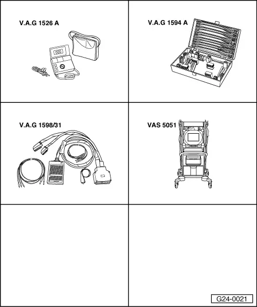
Special tools and workshop equipment required

  • ◆ V.A.G 1526 A
  • ◆ V.A.G 1594 A
  • ◆ V.A.G 1598/31
  • ◆ VAS 5051 with VAS 5051/1
  • or
  • ◆ V.A.G 1551 with V.A.G 1551/3 A

Note:

Charge pressure sender -G31 and its wiring are monitored by the engine control unit.

  • ‒ Connect vehicle diagnostic, testing and information system VAS 5051 (or fault reader V.A.G 1551) and select engine electronics control unit by entering address word "01"
    When doing this the engine must be idling.

=> Motronic injection and ignition system; Repair group 01; Self-diagnosis of Motronic system; Connecting vehicle diagnostic, testing and information system VAS 5051 or fault reader V.A.G 1551 and selecting functions

  • ‒ Interrogate fault memory of engine control unit.

=> Motronic injection and ignition system; Repair group 01; Interrogating and erasing fault memory

If the display shows a fault relating to charge pressure sender -G31:

Checking voltage supply

 
A10-0113
  • ‒ Switch off ignition.
  • ‒ → Lift off engine cover panel -arrows-.
  • ‒ Unplug connector on charge air pressure sender.

 
A24-0094
  • ‒ → Connect multimeter (voltage measurement range) between contacts 1 and 3 on connector.
  • ‒ Switch on ignition.
    • ‒ Specification: approx. 5 V

If the specification is not attained:

  • ‒ Connect test box V.A.G 1598/31 to wiring harness for engine control unit. Connect the engine control unit as well.

=> Motronic injection and ignition system; Repair group 24; Servicing Motronic injection system; Checking fuel pump relay and activation.

 
A24-0094
  • ‒ → Test for open circuit and short to positive or earth in the following wiring connections:

Connector
Contact

Test box V.A.G 1598/31
Socket

1

108

3

98

  • ‒ Rectify any open/short circuit as necessary.

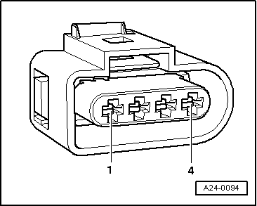
If the specification is obtained:

Testing signal wire

  • ‒ Unplug connector on charge pressure sender.
  • ‒ Connect multimeter (voltage measurement range) between sockets 101 and 108 on test box.
  • ‒ Start engine and run at idling speed.
    • ‒ Specification: approx 1.90 V
  • ‒ Increase engine speed by operating throttle quickly.
    • ‒ Specification: approx. 2.00 ... 3.00 V

If the specifications are not obtained:

 
A24-0094
  • ‒ → Test for open circuit and short to positive or earth in the following wiring connections:

Connector
Contact

Test box V.A.G 1598/31
Socket

4

101

  • ‒ Rectify any open/short circuit as necessary.

If the wiring is OK:

  • ‒ Renew charge pressure sender -G31.

Testing charge pressure control function via load signal > < Testing air recirculation valve for turbocharger -N249