
A4 Mk1
| Removing engine |

| Special tools and workshop equipment required |
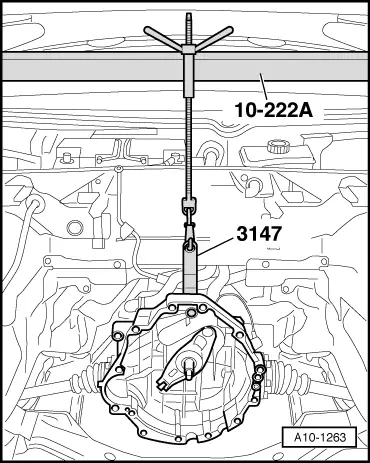
| t | Support bracket -10-222 A- |
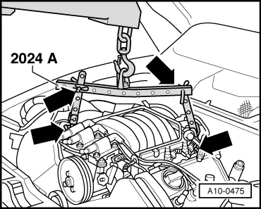
| t | Lifting tackle -2024 A- |
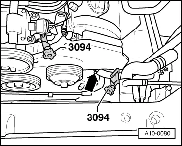
| t | Hose clamps for hoses up to 25 mm Ø -3094- |
| t | Gearbox support -3147- |
| t | Workshop hoist -V.A.G 1202 A- or -VAS 6100- |
| t | Drip tray for workshop hoist -VAS 6208- or -V.A.G 1306- |

| t | Locking pin -3204- |
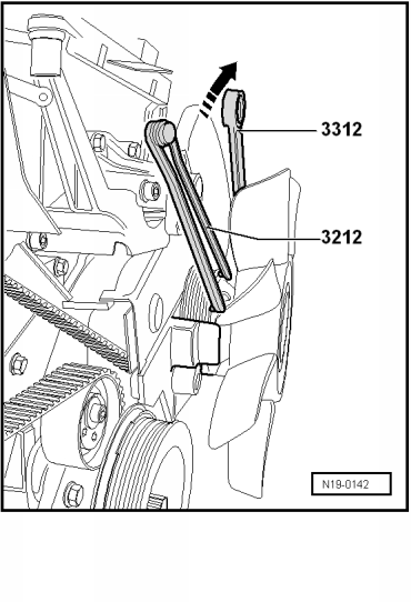
| t | 2-hole pin wrench -3212- |
| t | Open-end spanner -3312- |
|
|
 Note
Note
|
|
|
|
 Caution
|
|
|
|
 WARNING
|
|
|
|
|
|
|
|
|
|
|
|
Note
|
|
|
|
|
|
|
|
|

|
|
|
Note
|
|
Note
|
|
Note
|
|
|
|
|
|
|
|
|
|
|
|
|
|
|
|
|
|
|
|
|
|
|
|
|
|
|
|
|
|
|
|
Note
|
|
Note
|
|
|
|
|
|
|
|
Note
|
|
|
|
|
|
|
|
Note
|
|
|
|
Note
|
|
|
|
|
|
|
|
|
|
Note
|
|
|
|
Note
|
|
Note
Note
Note
|
|
|
|