| t
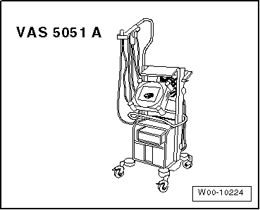
| Vehicle diagnostic, testing and information system -VAS 5051- |
| l
| Vehicle diagnostic, testing and information system -VAS 5051- with diagnosis lead -VAS 5051/1- is connected; vehicle self-diagnosis and vehicle system “01 - Engine electronics” is selected. |
| l
| Coolant temperature at least 80 °C. |
| l
| Vehicles with automatic gearbox: selector lever in position “P” or “N” |

WARNING | t
| Test equipment must always be secured on the rear seat and operated from that position by a second person. |
| t
| If test and measuring instruments are operated from front passenger's seat and the vehicle is involved in an accident, the person sitting in this seat could be seriously injured when the airbag is triggered. |
|
| –
| Start engine and run at idling speed. |
|
|
|

 Note
Note