
A4 Mk1
 Note
Note
|
|
|
|
|
|
|
 WARNING
|
|
|
|
|
|
|
|
|
|
|
|
|
|
|
|
Note
Note
|
|
| Component | Nm | ||
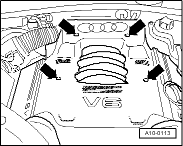
| Intake manifold to cylinder head | 10 | ||
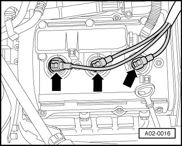
| Fuel pipes to fuel rail/fuel pressure regulator | 23 | ||
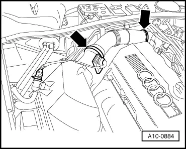
| Air duct to intake manifold | 10 | ||