
A4 Mk1
|
|
|
|
|
 Note
Note
|
|
|
|
|
|
|
|
|
|
|
|
|
|
|
|
|
|
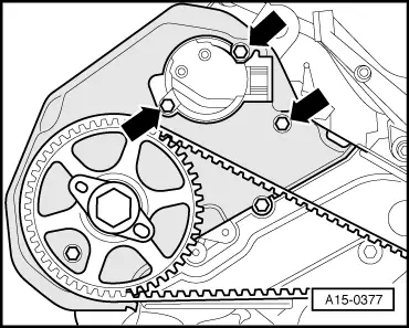
| Component | Nm | ||
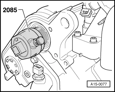
| Hall sender rotor to camshaft | 25 | ||
| Hall sender housing to cylinder head | 10 | ||
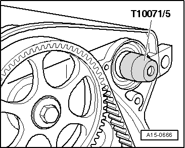
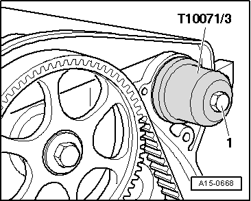
| Rear toothed belt cover to cylinder head | 10 1) | ||
| |||