audi Workshop Repair Guides

Audi Workshop Service and Repair Manuals

Securing engine to assembly stand > < Removing engine
Separating engine and gearbox
Special tools and workshop equipment required
t  
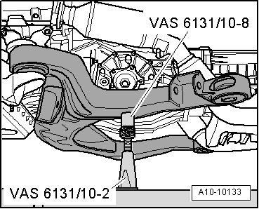
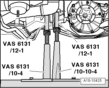
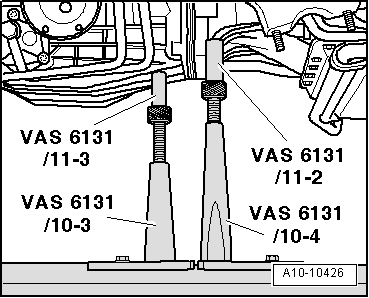
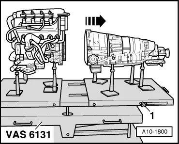
Support set for Audi -VAS 6131/10-, plate -VAS 6131/10-1- and supplementary set -VAS 6131/11- and -VAS 6131/12-
Procedure
l  Engine/gearbox assembly removed and in position on scissor-type assembly platform -VAS 6131-.
  Note
t  All heat insulation sleeves which are removed must be fitted in the same position when installing.
t  All cable ties which are released or cut open when removing must be fitted in the same position when installing.
   
–  Unscrew bolts -1- and -2- for gearbox mounting (left and right).
  A17-0043
–  Screw down spindles of the support elements (left and right) at subframe as far as possible.
–  Remove locating lugs from spindles.
–  Remove subframe to the side.
–  Unscrew the two base plates for support elements (for subframe) on scissor-type assembly platform -VAS 6131-.
  A10-10133
–  Take electrical connector -2- for Lambda probe 2 -G108- out of bracket (left-side) and unplug it.
–  Remove heat insulation sleeve at wiring harness and move the wiring clear.
  Note
Illustration shows electrical connectors when installed.
  A10-0299
–  Take electrical connector -2- for Lambda probe 2 after catalytic converter -G131- out of bracket (right-side) and unplug it.
–  Remove heat insulation sleeve at wiring harness and move the wiring clear.
  Note
Illustration shows electrical connectors when installed.
  A10-0856
–  Unscrew bolt -2- at bracket for front exhaust pipe (left-side).
  Note
Disregard -item 1-.
  A26-10251
–  Slacken clip -1-.
–  Unscrew bolts -2- and -3- and remove heat shield from front exhaust pipe (left-side).
  A26-10253
–  Unscrew nuts -1 ... 4- securing front exhaust pipe to turbocharger (left-side).
–  Take out front exhaust pipe with starter and main catalytic converter.
  A26-10255
–  Take electrical connectors -1- and -3- for Lambda probe -G39- and Lambda probe after catalytic converter -G130- out of bracket (right-side) and unplug.
–  Move wiring clear.
  Note
Illustration shows electrical connectors when installed.
  A10-0856
–  Unscrew bolt -1- at bracket for front exhaust pipe (right-side).
  Note
Disregard -item 1-.
  A26-10252
–  Unbolt exhaust gas temperature sender 1 -G235--item 2- from turbocharger.
–  Slacken clip -1-.
–  Unscrew bolts -3- and -4- and remove heat shield from front exhaust pipe (right-side).
  A26-10254
–  Unscrew nuts -1 ... 4- securing front exhaust pipe to turbocharger (left-side).
–  Take out front exhaust pipe with starter and main catalytic converter.
  A26-10256
–  Unplug electrical connector -arrow- at speedometer sender -G22- on gearbox.
  A10-0947
–  Unbolt engine speed sender -G28- from gearbox -arrow-.
  A34-0119
–  Unplug electrical connector -arrow- at reversing light switch -F4- and move wiring clear.
  Note
  A34-0497
Lay a cloth under the separating point to catch any escaping gear oil.
–  Loosen union nuts -1- and -2-.
–  Remove bracket for gear oil pipes by unscrewing nut -3-.
–  Set up scissor-type assembly platform -VAS 6131- with support set for Audi -VAS 6131/10-, supplementary set -VAS 6131/11- and -VAS 6131/12- as follows:
  A37-10394
Platform coordinatesParts of support set for Audi -VAS 6131/10-, -VAS 6131/11- and -VAS 6131/12-
C3/10-1/10-4/10-5/10-11
G3 1)/10-1/10-4/10-5/10-12
C7/10-1/10-4/10-5/12-1
F7/10-1/10-4/10-5/11-2
C10/10-1/10-4/10-5/12-1
F10/10-1/10-3/10-5/11-3
F13/10-1/10-3/10-5/10-11
C15/10-1/10-4/10-5/10-13
l  1) Support elements remain unchanged

   
–  Remove bottom engine/gearbox securing bolts -arrows-.
  A17-10067
–  Position support elements from -VAS 6131/10- and -VAS 6131/12- on left side of engine/gearbox assembly, as shown in illustration.
  A10-10425
–  Position support elements from -VAS 6131/10- and -VAS 6131/11- on right side of engine/gearbox assembly, as shown in illustration.
–  Turn spindles for the support elements upwards until all locating lugs make contact with the mounting points.
–  Tighten base plates for support elements to 20 Nm on scissor-type assembly platform -VAS 6131-.
  A10-10426
–  Remove engine/gearbox securing bolts -1 ... 4- and -7-.
  A10-0193
–  Loosen the clamping bolts -1- on sides of scissor-type assembly platform -VAS 6131- and pull rear section of platform together with the gearbox towards rear -arrow-.
  A10-1800

Securing engine to assembly stand > < Removing engine