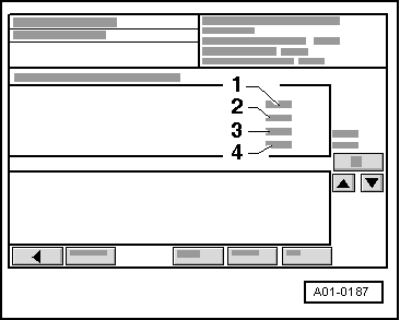
audi Workshop Repair Guides

Audi Workshop Service and Repair Manuals

Checking camshaft control valves (solenoid valves) > < Checking variable valve timing
Checking function of variable valve timing
  Note
The variable valve timing is not activated until about 25 seconds after the engine has started.
Special tools and workshop equipment required
   
t  Vehicle diagnostic, testing and information system -VAS 5051-
Procedure
l  Coolant temperature at least 80 °C.
  WARNING
t  Test equipment must always be secured on the rear seat and operated from that position by a second person.
t  If test and measuring instruments are operated from front passenger's seat and the vehicle is involved in an accident, the person sitting in this seat could be seriously injured when the airbag is triggered.
  W00-10343
–  Open rear ashtray and remove cover for diagnostic connector.
  A24-0028
–  Connect up vehicle diagnostic, testing and information system -VAS 5051- with diagnosis lead -VAS 5051/1-, press vehicle self-diagnosis button and select vehicle system “01 - Engine electronics”. Engine must be idling.
  A01-0061
Display on -VAS 5051-:
–  From the list -1- select diagnostic function “08 - Read measured value block”.
  A01-0122
Display on -VAS 5051-:
1 - Enter display group
–  Use keypad -2- to enter “90” for “Display group number 090” and confirm by touching the Q key.
  A01-0130
Display on -VAS 5051-:
l  Engine running at idling speed.
–  Check display in zones -2-, -3- and -4-.
  A01-0187
Display zonesExplanatory notes
2---Variable valve timing
l  Specification: “CS-ctrl.OFF”
3... °CAVariable valve timing bank 1 (cylinder bank right-side)
l  Specification: -3 ... 6  CA
4... °CAVariable valve timing bank 2 (cylinder bank left-side)
l  Specification: -3 ... 6  CA

–  Perform road test and have a second mechanic check display in zones -2-, -3- and -4-.
   
Display zonesExplanatory notes
2---Variable valve timing
l  Specification: “CS-ctrl.ON”
3... °CAVariable valve timing bank 1 (cylinder bank right-side)
l  Specification: 16 ... 25  CA 1)
4... °CAVariable valve timing bank 2 (cylinder bank left-side)
l  Specification: 16 ... 25  CA 1)
l  1) If the readout only shows a value between 6.0° CA (crankshaft angle) and 16.0° CA during the test drive, this indicates that the camshaft control valve is working correctly and feeding the oil pressure to the camshaft adjustment mechanism, but the mechanism is not able to reach its end position (possibly because it is not moving freely).

–  Press the  key to exit from the function “08 - Read measured value block”.
If the specifications are not obtained:
–  Check the camshaft control valves → Chapter.
If the specifications are obtained:
–  Press “06 - End output”.
–  Switch off ignition and unplug diagnostic connector.
   

Checking camshaft control valves (solenoid valves) > < Checking variable valve timing