audi Workshop Repair Guides

Audi Workshop Service and Repair Manuals

Checking hydraulic bucket tappets > < Renewing oil seal for Hall sender - cylinder head (right-side)
Removing and installing camshafts and camshaft adjuster
Special tools and workshop equipment required
   
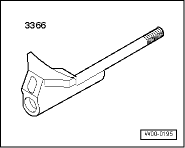
t  Chain tensioner retainer -3366-
t  Sealant → Parts catalogue
  W00-0195
Removing
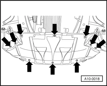
–  Remove noise insulation -arrows-.
–  Remove front bumper → Rep. Gr.63.
–  Move lock carrier to service position → Rep. Gr.50.
–  Remove toothed belt → Chapter.
–  Take off camshaft sprocket.
–  Unscrew toothed belt cover (rear).
–  Remove cylinder head cover: left-side → Chapter, right-side → Chapter.
–  Unplug electrical connector at camshaft adjuster.
–  Remove Hall sender → Item and Hall sender rotor → Item.
–  Turn the crankshaft approx. 45° anti-clockwise at the toothed belt sprocket bolt so that all pistons are clear of TDC position.
  A10-0018
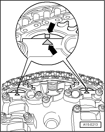
–  Check TDC position of camshafts again:
l  The two marks on the camshafts must be opposite the two arrows on the bearing caps -arrows-.
  A15-0213
If old drive chain is to be reused:
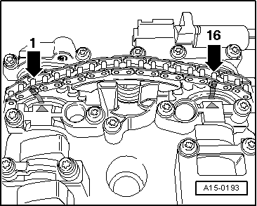
–  Clean drive chain and sprockets of camshafts opposite the two arrows on the bearing caps and mark installation position with a coloured dot.
l  The distance between the two arrows (and thus between the coloured markings) is 16 rollers on the chain.
l  Notch on exhaust camshaft has a slight inward offset with respect to chain roller -1-.
  Note
Do not mark chain with a centre punch or by making a notch or similar.
  A15-0193
Continued for all drive chains:
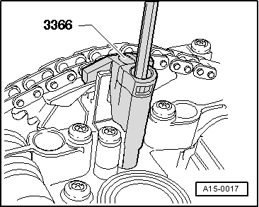
–  Hold camshaft adjuster in position with chain tensioner retainer -3366-.
  Note
Over-tightening retainer for chain tensioner can damage the camshaft adjuster.
  A15-0017
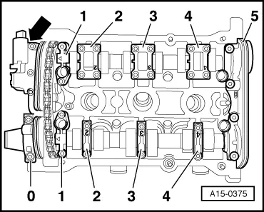
–  Mark the sequence and installation positions of all bearing caps, as shown, regardless of any existing markings on the bearing caps.
–  Unscrew bolts securing camshaft adjuster -arrow-.
–  Remove bearing cap -0-.
–  Remove bearing caps -1-, -3- and -5- and place them in the correct order on a clean surface.
–  Slacken off bearing caps -2- and -4- of inlet and exhaust camshafts alternately and diagonally, and remove.
–  Lift out both camshafts with camshaft adjuster.
  A15-0375
Installing
Installation is carried out in the reverse order; note the following:
–  Renew the semi-circular sealing plug.
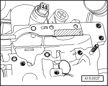
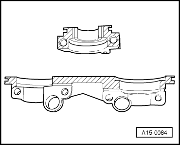
–  Renew rubber/metal gasket for camshaft adjuster and apply a thin coat of sealant to the -hatched area-; Sealant → Parts catalogue.
  A15-0027
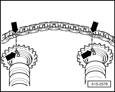
–  Position drive chain as follows on camshaft chain sprockets:
If old drive chain is to be reused:
l  Adjust the colour markings -arrows- so they are aligned.
If new drive chain is being used:
  Caution
t  The stated number of rollers merely provides assistance for fitting the drive chain onto the camshafts.
t  Make sure that the arrows on the bearing caps and the notches on the camshafts align when installing camshafts (with drive chain) in cylinder head → Anchor.
  A15-0378
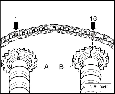
Cylinder head (left-side):
l  The distance between notches -A- and -B- on the camshafts must be 16 drive chain rollers. The illustration shows the exact positions of the 1st and 16th rollers on the sprockets.
l  The chain rollers -1- and -16- are offset 1/2 tooth outwards in relation to notches -A- and -B-
  A15-10044
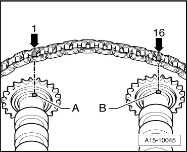
Cylinder head (right-side):
l  The distance between notches -A- and -B- on the camshafts must be 16 drive chain rollers. The illustration shows the exact positions of the 1st and 16th rollers on the sprockets.
l  The chain rollers -1- and -16- are located vertically above notches -A- and -B-.
Continued for all drive chains:
–  Insert camshaft adjuster into the chain (2nd mechanic required).
–  Insert camshafts with drive chain and camshaft adjuster into cylinder head.
–  Lubricate running surfaces of camshafts.
l  Dowel sleeves for bearing caps and camshaft adjuster must be positioned in cylinder head
  A15-10045
–  Secure camshaft adjuster -arrow- (watch position of dowel sleeves).
–  Install bearing caps -2- and -4- as per marking.
–  Tighten bearing caps -2- and -4- of inlet camshaft and exhaust camshaft alternately in diagonal sequence.
–  Install the two bearing caps -1- next to the chain sprockets on the inlet and exhaust camshafts.
–  Remove chain tensioner retainer -3366-.
  A15-0375
–  Check correct setting of camshafts:
l  The two marks on the camshafts must be opposite the two arrows on the bearing caps -arrows-.
  Note
If necessary, turn camshaft slightly backwards or forwards so that the two marks coincide.
  A15-0213
–  Apply a small quantity of sealant to the -hatched area- of the double bearing cap and the outer bearing cap adjacent to the camshaft adjuster; Sealant → Parts catalogue.
–  Install bearing cap (pay attention to dowel sleeves).
–  Install remaining bearing caps (pay attention to dowel sleeves).
–  Renew oil seals for inlet and exhaust camshaft → Chapter, → Chapter or → Chapter.
–  Torque down remaining bearing caps.
–  Turn the crankshaft approx. 45° clockwise back to TDC at the toothed belt sprocket bolt and secure crankshaft with locking pin.
–  Install cylinder head cover: left-side → Chapter, right-side → Chapter.
–  Install toothed belt (adjust valve timing) → Anchor.
–  Install vibration damper → Chapter.
–  Install poly V-belt → Chapter.
–  Install viscous fan → Chapter.
–  Install lock carrier with attachments → Rep. Gr.50.
–  Install front bumper → Rep. Gr.63.
  Note
t  After installing camshafts, wait for approx. 30 minutes before starting engine. Hydraulic valve compensation elements have to settle (otherwise valves will strike pistons).
t  After working on the valve gear, turn the engine carefully at least 2 rotations by hand to ensure that none of the valves make contact when the starter is operated.
Tightening torques
  A15-0084
ComponentNm
Bearing cap to cylinder head10
Camshaft adjuster to cylinder head10
Hall sender rotor to camshaft25
Hall sender housing to cylinder head10
Toothed belt cover (rear) to cylinder head/ cylinder block10 1)
l  1) Install bolts using locking fluid; locking fluid → Parts catalogue.


Checking hydraulic bucket tappets > < Renewing oil seal for Hall sender - cylinder head (right-side)