audi Workshop Repair Guides

Audi Workshop Service and Repair Manuals

Valve dimensions > < Checking hydraulic bucket tappets
Renewing valve stem oil seals
   
Renewing valve stem oil seals
Special tools and workshop equipment required
t  Pressure hose -VW 653/3-
t  Spark plug socket and extension -3122 B-
t  Valve stem seal puller -3364-
t  Valve stem seal fitting tool -3365-
t  Disassembly and assembly tool -VAS 5161-

Procedure
l  Cylinder head installed.
–  Remove camshafts and camshaft adjuster → Chapter.
  Note
Use waterproof felt-tip pen to mark assignment of bucket tappets on back to ensure that the tappets are not interchanged.
   
–  Remove the bucket tappets from the guides and put them down with the contact surface downwards.
–  Remove spark plugs with spark plug socket -3122 B-.
–  Set piston of the respective cylinder to “bottom dead centre”.
–  Connect pressure hose -VW 653/3- to compressed air supply.
l  Air pressure: at least 6 bar
–  Insert punch -VAS 5161/3- into bucket tappet guide.
–  Knock valve cotters on all five valves loose using a plastic hammer.
  A15-0544
Inlet side:
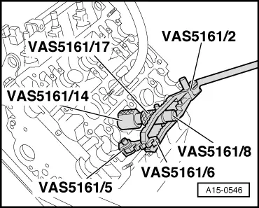
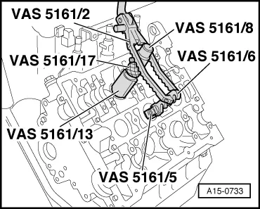
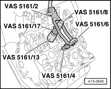
–  Screw snap-in device -VAS 5161/6- with interlocking fork -VAS 5161/4- onto stud on cylinder head.
–  Push guide bush -VAS 5161/13- as far as it will go into bucket tappet guide for valve to be removed.
l  Installation position: knurled surfaces face perpendicular to direction of travel.
–  Slide knurled spacer ring -VAS 5161/17- onto assembly cartridge -VAS 5161/8-.
–  Insert assembly cartridge into guide bush.
–  Attach pressure fork -VAS 5161/2- to snap-in device -VAS 5161/6- and push assembly cartridge down.
–  At the same time, turn knurled screw of assembly cartridge clockwise until tips engage in valve cotters.
–  Move knurled screw back and forth slightly; the valve cotters are thus forced apart and taken up by the cartridge.
–  Release the pressure fork.
–  Take off assembly cartridge with knurled spacer ring.
–  Remove guide bush, valve spring plate and valve spring.
  A15-0545
Exhaust side:
–  Screw snap-in device -VAS 5161/6- with interlocking fork -VAS 5161/5- into threaded hole on cylinder head.
–  Push guide bush -VAS 5161/14- as far as it will go into bucket tappet guide for valve to be removed.
l  Installation position: knurled surfaces face perpendicular to direction of travel.
–  Slide knurled spacer ring -VAS 5161/17- onto assembly cartridge -VAS 5161/8-.
–  Insert assembly cartridge into guide bush.
–  Attach pressure fork -VAS 5161/2- to snap-in device -VAS 5161/6- and push assembly cartridge down.
–  At the same time, turn knurled screw of assembly cartridge clockwise until tips engage in valve cotters.
–  Move knurled screw back and forth slightly; the valve cotters are thus forced apart and taken up by the cartridge.
–  Release the pressure fork.
–  Take off assembly cartridge with knurled spacer ring.
–  Remove guide bush, valve spring plate and valve spring.
  A15-0546
Continuation for both sides:
–  Remove valve stem oil seal using the valve stem seal puller -3364-.
  A15-0547
If the valve stem seal puller -3364- cannot be used on some of the valve stem oil seals due to the confined space, proceed as follows:
–  Knock pin -arrow- of valve stem seal puller -3364- out using a punch and remove the extractor attachment.
  A15-0493
–  Apply lower part of valve stem seal puller -3364- to valve stem oil seal.
–  Secure valve stem seal puller -3364- with a punch -1- or other suitable tool, as illustrated.
–  Apply an assembly lever to puller -3364- and pull out valve stem oil seal -arrow-.
  Note
  A15-0562
A plastic sleeve -A- is included with the new valve stem oil seals.
–  To prevent damage to the new valve stem seals -B-, attach plastic sleeve -A- to valve stem.
–  Lightly oil sealing lip of valve stem oil seal.
–  Slip valve stem oil seal over plastic sleeve.
–  Carefully press valve stem oil seal onto valve guide using valve stem seal fitting tool -3365-.
–  Remove the plastic sleeve.
  Note
Ensure correct positioning in cylinder head when fitting valve springs of exhaust valves (otherwise assembly is not possible).
  A15-0282
If valve cotters have been removed from assembly cartridge, they need to be put into insertion device -VAS 5161/18- first.
l  Larger diameter of valve cotters faces upwards.
–  Press assembly cartridge onto valve insertion device from above and take up valve cotters.
–  Insert guide bush -VAS 5161/13- or -VAS 5161/14-, valve spring and valve spring plate.
  A15-0445
–  Re-insert cartridge into guide bush.
–  Push pressure fork down and pull knurled screw upwards while turning screw in both directions - this will insert the valve cotters.
–  Release the pressure fork with knurled screw still in pulled position.
Installation is carried out in the reverse order; note the following:
–  Insert bucket tappets.
–  Install spark plugs → Rep. Gr.28.
–  Install camshafts and camshaft adjuster → Chapter.
  Note
t  After installing camshafts, wait for approx. 30 minutes before starting engine. Hydraulic valve compensation elements have to settle (otherwise valves will strike pistons).
t  After working on the valve gear, turn the engine carefully at least 2 rotations to ensure that none of the valves make contact when the starter is operated.
  A15-0733

Valve dimensions > < Checking hydraulic bucket tappets