
A4 Mk1
| Pistons and conrods - exploded view of components |
 Note
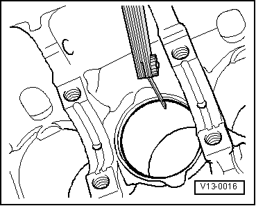
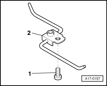
Note| Oil spray jet for piston cooling → Fig.. |

| 1 - | Conrod bolt, 30 Nm + 90° (1/4 turn) further |
| q | Renew |
| q | Lubricate threads and contact surface |
| q | To measure radial clearance, tighten to 30 Nm but do not turn further |
| 2 - | Conrod bearing cap |
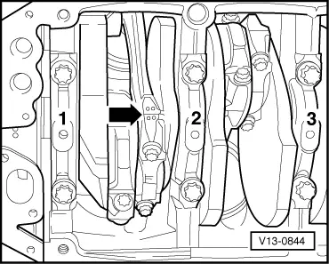
| q | Note installation position: split contact surfaces on side of conrod must be in alignment -B- |
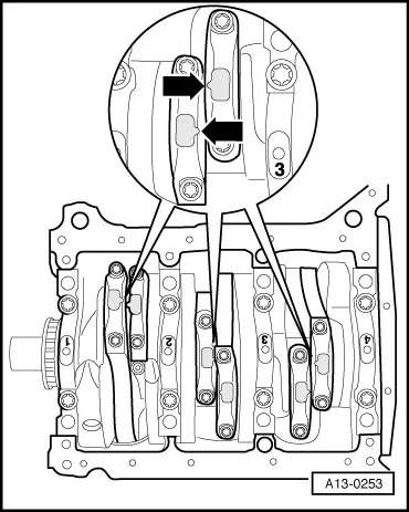
| 3 - | Bearing shell |
| q | Note installation position |
| q | Do not interchange used bearing shells (mark positions) |
| q | Note type: upper bearing shell (closest to piston) is made of more wear-resistant material. Distinguishing feature on new bearing shells: black marking on contact surface near separating point |
| q | Check that it is securely seated |
| q | Measuring radial clearance → Chapter |
| q | To measure radial clearance, tighten bolts → Item to 30 Nm but do not turn further |
| 4 - | Conrod |
| q | Only renew as a complete set |
| q | Mark cylinder allocation -A- → Fig. |
| q | Note when fitting bearing cap: split contact surfaces on side of conrod must be in alignment -B- |
| q | Installation position of conrod pairs → Fig. |
| 5 - | Circlip |
| 6 - | Piston pin |
| q | If difficult to move, heat piston to approx. 60 °C |
| q | Remove and install using drift -VW 222 A- |
| 7 - | Piston |
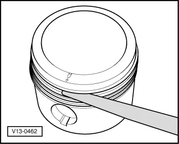
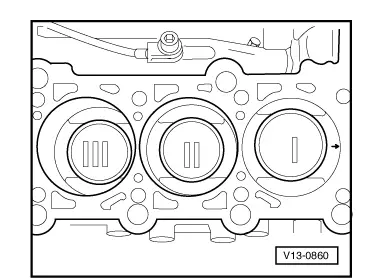
| q | Mark installation position and cylinder number → Fig. |
| q | Arrow on piston crown points to pulley end |
| q | Checking → Fig. |
| q | Install using piston ring clamp |
| q | Piston and cylinder dimensions → Chapter |
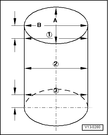
| q | Checking cylinder bore → Fig. |
| 8 - | Piston rings |
| q | Offset gaps by 120° |
| q | Use piston ring pliers to remove and install |
| q | “TOP” must face towards piston crown |
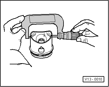
| q | Checking ring gap → Fig. |
| q | Checking ring-to-groove clearance → Fig. |
| Piston ring Dimensions in mm | New | Wear limit |
| 1st compression ring | 0.35 … 0.50 | 1.0 |
| 2nd compression ring | 0.50 … 0.70 | 1.4 |
| Oil scraper ring | 0.25 … 0.50 | 0.8 |
|
|
| Piston ring Dimensions in mm | New | Wear limit |
| Compression rings | 0.02 … 0.08 | 0.10 |
| Oil scraper ring | 0.02 … 0.08 | 0.10 |
|
|
|
|
Note
|
|
Note
|
|
|
|
|
|