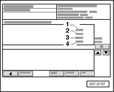
audi Workshop Repair Guides

Audi Workshop Service and Repair Manuals

Checking exhaust gas temperature sender > < Exhaust gas temperature monitoring
Checking function of exhaust gas temperature monitoring
Special tools and workshop equipment required
   
t  Vehicle diagnostic, testing and information system -VAS 5051-
Procedure
  WARNING
t  Test equipment must always be secured on the rear seat and operated from that position by a second person.
t  If test and measuring instruments are operated from front passenger's seat and the vehicle is involved in an accident, the person sitting in this seat could be seriously injured when the airbag is triggered.
l  Coolant temperature at least 80 °C.
  W00-10343
–  Open rear ashtray and remove cover for diagnostic connector.
  A24-0028
–  Connect up vehicle diagnostic, testing and information system -VAS 5051- with diagnosis lead -VAS 5051/1-, press vehicle self-diagnosis button and select vehicle system “01 - Engine electronics”. Engine must be idling.
  A01-0061
Display on -VAS 5051-:
–  From the list -1- select diagnostic function “08 - Read measured value block”.
  A01-0122
Display on -VAS 5051-:
1 - Enter display group
–  Use keypad -2- to enter “112” for “Display group number 112” and confirm by touching the Q button.
  A01-0130
Display on -VAS 5051-:
–  Perform road test at full throttle and at engine speeds between 5000 ... 6500 rpm and have a second mechanic check display in zones -1 ... 4-
  A01-0187
Display zonesExplanatory notes
1... °CExhaust gas temperature bank 1 (cylinder bank right-side)
l  Specification 980 °C 1)2)3)
2… %Enrichment factor Sensor Bank 1 (cylinder bank right-side)
l  Specification: 20 ± 5 % 4)
3... °CExhaust gas temperature bank 2 (cylinder bank left-side)
l  Specification 980 °C 1)2)3)
4… %Enrichment factor Sensor Bank 2 (cylinder bank left-side)
l  Specification: 20 ± 5 % 4)
l  1)“945 °C” is displayed at an exhaust gas temperature of 945 °C or below.
l  2) The control process is activated when the exhaust gas temperature is above 980 °C.
l  3) During the start-up period, the display can rise to 1025 °C.
l  4) Possible causes of the displayed values constantly exceeding 30 % can be either low fuel pressure or that the signal transmitted by the air mass meter -G70- is too small.

   
–  Press the key.
Display on -VAS 5051-:
1 - Enter display group
–  Use keypad -2- to enter “220” for “Display group number 220” and confirm by touching the Q button.
  A01-0130
Display on -VAS 5051-:
–  Continue to drive at full throttle and at engine speeds between 5000 ... 6500 rpm and have a second mechanic check display in zones -1 ... 4-.
  A01-0187
Display zonesExplanatory notes
1... rpmEngine speed
l  Specification: above 5000 rpm
2… %Load
l  Specification: Above 100 %
3… %Duty cycle, exhaust gas temperature sender 1 -G235-
l  Specification: 42 ± 10 %
4Operating status, bank 1 (cylinder bank right-side)
l  Specification: Control ON

–  Switch to “display group 221” by touching the key.
–  Continue to drive at full throttle and at engine speeds between 5000 ... 6500 rpm and have a second mechanic check display in zones -1 ... 4-.
   
Display zonesExplanatory notes
1... rpmEngine speed
l  Specification: above 5000 rpm
2… %Load
l  Specification: Above 100 %
3… %Duty cycle, exhaust gas temperature sender 1, bank 2 -G236-
l  Specification: 42 ± 10 %
4Operating status, bank 2 (cylinder bank left-side)
l  Specification: Control ON

–  Press the  key to exit from the function “08 - Read measured value block”.
–  Press “06 - End output”.
–  Terminate road test, switch off ignition and unplug diagnostic connector.
If the specifications are not obtained:
–  Check exhaust gas temperature sender → Chapter.
   

Checking exhaust gas temperature sender > < Exhaust gas temperature monitoring