
A4 Mk1
|
|
|
 Note
Note
|
|
Note
|
|
|
|
|
|
|
|
|
|
|
|
|
|
|
|
|
|
|
|
|
|
|
|
|
|
|
|
Note |
|
Note
|
|
|
|
|
|
Note |
|
Note
|
|
|
|
Note
Note
|
|
| Component | Nm | |||
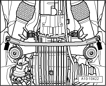
| Front exhaust pipe with starter catalytic converter and main catalytic converter to: | Turbocharger | 30 1) | ||
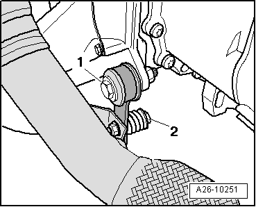
| Mounting bracket | 25 | |||
| Mounting bracket to gearbox support | 25 | |||
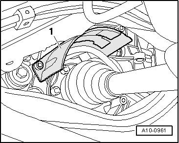
| Drive shaft heat shield to gearbox | 23 | |||
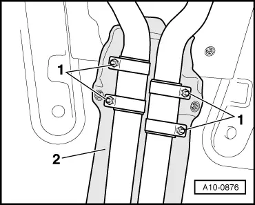
| Heat shield for front exhaust pipe | 10 | |||
| Air duct to intake manifold | 10 | |||
| ||||