
A4 Mk1
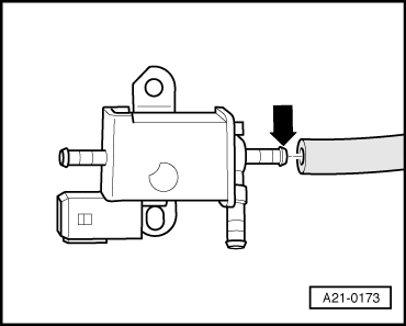
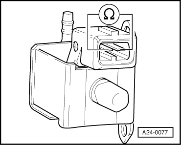
| Checking secondary air inlet valve -N112- |

| Special tools and workshop equipment required |
| t | Hand-held multimeter -V.A.G 1526 C- or -V.A.G 1526 A- |
| t | Voltage tester -V.A.G 1527 B- |
| t | Auxiliary measuring set -V.A.G 1594 C- or -V.A.G 1594 A- |
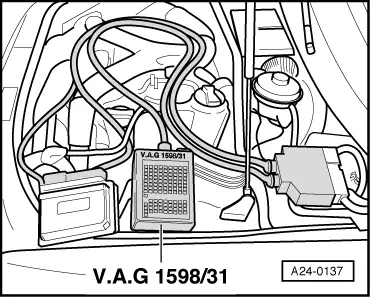
| t | Adapter cable -V.A.G 1598/31- (test box) |
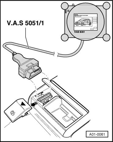
| t | Vehicle diagnosis, testing and information system -VAS 5051- |
 Note
Note
|
|
|
|
|
|
|
|
|
|
|
|
|
|
|
|
|
|
Note
|
|
|
|
|
|
|
|
|
|
 Caution
|
|
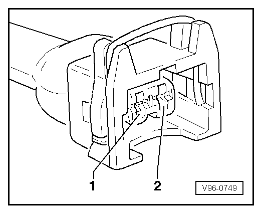
| Connector Contact | Adapter cable -V.A.G 1598/31- (test box) Socket |
| -2- | 44 |
|