audi Workshop Repair Guides

Audi Workshop Service and Repair Manuals

Checking air recirculation valve for turbocharger N249 > < Checking solenoid valve for charge pressure control N75
Checking charge pressure senderG31
   
Checking charge pressure sender -G31-
Special tools and workshop equipment required
t  Hand-held multimeter -V.A.G 1526 C- or -V.A.G 1526 A-
t  Auxiliary measuring set -V.A.G 1594 C- or -V.A.G 1594 A-
t  Adapter cable -V.A.G 1598/31- (test box)
t  Vehicle diagnostic, testing and information system -VAS 5051- with diagnosis lead -VAS 5051/1-

   
Procedure
  Note
The charge pressure sender -G31- and the wiring connections are monitored by the engine control unit.
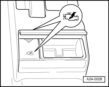
–  Open rear ashtray and remove cover for diagnostic connector.
  A24-0028
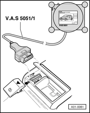
–  Connect up vehicle diagnostic, testing and information system -VAS 5051- with diagnosis lead -VAS 5051/1-, press vehicle self-diagnosis button and select vehicle system “01 - Engine electronics”. When doing this, the engine must be running at idling speed.
  A01-0061
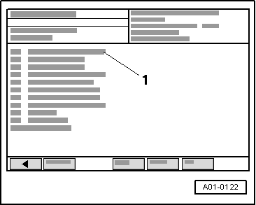
Display on -VAS 5051-:
–  From list -1-, select diagnosis function “02 - Interrogate fault memory”.
If a fault relating to charge pressure sender -G31- is displayed:
–  Terminate function “02 - Interrogate fault memory” by touching key.
–  Press function “06 - End output”.
–  Switch off ignition and unplug diagnostic connector.
  A01-0122
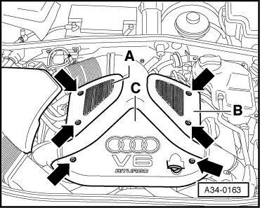
–  Unfasten screw connections -bottom arrows- and detach front engine cover panel -C-.
  A34-0163
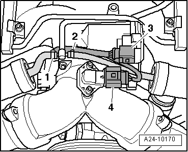
–  Unplug electrical connector at charge pressure sender -G31--item 4-.
  Note
Disregard -items 1 ... 3-.
  A24-10170
Checking voltage supply
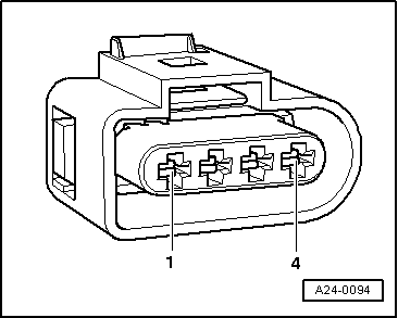
–  Connect hand-held multimeter -V.A.G 1526 C- to measure voltage between contacts -1- and -3- of connector for charge pressure sender -G31-.
–  Switch on ignition.
l  Specification: approx. 5 V
  A24-0094
If specification is not obtained:
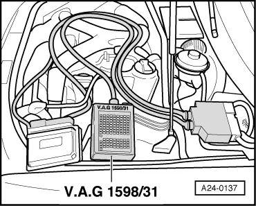
–  Connect adapter cable -V.A.G 1598/31- (test box) to connectors of wiring harness; do not connect engine control unit. Connect earth clip of test box to earth (not shown in illustration).
  Caution
To prevent damage to electronic components, select appropriate measuring range before connecting measuring leads and observe test requirements.
  A24-0137
–  Check for open circuit and short to positive or earth in the following wiring:
  A24-0094
Connector
Contact
Adapter cable -V.A.G 1598/31- (test box)
Socket
-1-108
-3-98

–  Repair wiring connection if necessary.
If specification is obtained:
Checking signal wire
–  Plug in connector at charge pressure sender -G31-.
–  Connect hand-held multimeter -V.A.G 1526 C- (voltage measurement range) between sockets “101” and “108” on test box.
–  Start engine and run at idling speed.
l  Specification: approx. 1.90 V
–  Increase engine speed by depressing accelerator pedal briefly.
l  Specification: 2.00 ... 3.00 V
If the specifications are not obtained:
   
–  Check for open circuit and short to positive or earth in the following wiring:
  A24-0094
Connector
Contact
Adapter cable -V.A.G 1598/31- (test box)
Socket
-4-101

–  Repair wiring connection if necessary.
If wiring is OK:
–  Renew charge pressure sender -G31-.
   

Checking air recirculation valve for turbocharger N249 > < Checking solenoid valve for charge pressure control N75