
A4 Mk1
|
|
|
 Note
Note
|
|
|
|
|
|
Note
|
|
Note
|
|
Note
|
|
|
|
|
|
|
|
|
|
|
|
|
|
|
|
|
|
|
|
Note
Note
|
|
| Component | Nm | ||||
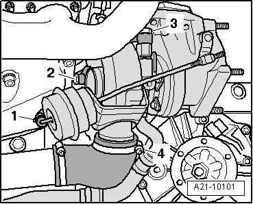
| Turbocharger to exhaust manifold | 60 1)2) | ||||
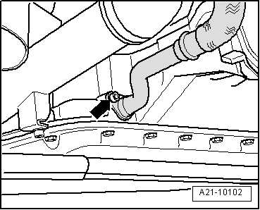
| Coolant line to turbocharger | 35 | ||||
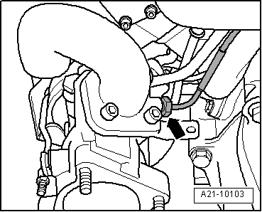
| Oil supply pipe to turbocharger | 30 | ||||
| Pressure line to turbocharger | 9 | ||||
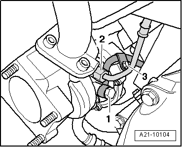
| Oil return pipe to sump (top section) | 10 | ||||
| Air pipe (left-side) to bracket | 22 | ||||
| Air pipe to cylinder head cover | 10 | ||||
| Hose clips (9 mm wide) | 3 | ||||
| Hose clips (13 mm wide) | 5.5 | ||||
| |||||