audi Workshop Repair Guides

Audi Workshop Service and Repair Manuals

Charge air cooling - air flow > < Removing and installing turbocharger (left-side)
Removing and installing turbocharger (right-side)
Special tools and workshop equipment required
   
t  Used oil collection and extraction unit -V.A.G 1782-
  W00-10211
Removing
  Note
t  All heat insulation sleeves which are removed must be fitted in the same position when installing.
t  All cable ties which are released or cut open when removing must be fitted in the same position when installing.
–  Remove noise insulation -arrows-.
–  Place used oil collection and extraction unit -V.A.G 1782- under engine.
–  Drain off engine oil.
–  Remove engine → Chapter.
–  Leave engine on scissor-type assembly platform -VAS 6131- with gearbox attached.
  A10-0018
–  Unscrew bolts -1- and -2- for gearbox mounting (left and right).
  A17-0043
–  Screw down spindles of the support elements (left and right) at subframe as far as possible.
–  Remove locating lugs from spindles.
–  Remove subframe to the side.
  A10-10133
–  Take electrical connectors for Lambda probe after catalytic converter -G130--1- and Lambda probe -G39--3- out of bracket (right-side) and unplug.
–  Remove heat insulation sleeve at wiring harness and move the wiring clear.
  Note
Illustration shows electrical connectors when installed.
  A10-0856
–  Unscrew bolt -1- at bracket for front exhaust pipe (right-side).
  Note
Disregard -item 2-.
  A26-10252
–  Unbolt exhaust gas temperature sender 1 -G235--item 2- from turbocharger.
–  Slacken clip -1-.
–  Unscrew bolts -3- and -4- and remove heat shield from front exhaust pipe (right-side).
  A26-10254
–  Unscrew nuts -1 ... 4- securing front exhaust pipe to turbocharger (right-side).
–  Take out front exhaust pipe with starter and main catalytic converter.
  A26-10256
–  Remove gear oil pipes from bracket by unscrewing nut -2-.
  Note
Disregard items marked -1- and -3-.
  Note
  A10-0952
Lay a cloth under the separating point to catch any escaping gear oil.
–  Loosen union nuts -1- and -2-.
–  Remove bracket for gear oil pipes by unscrewing nut -3-.
–  Remove gear oil pipes.
  A37-10394
–  Unscrew bolt -arrow- and detach oil return pipe from top section of sump.
  A21-10106
–  Detach vacuum hose -4-.
–  Unscrew banjo bolt -3- for pressure pipe.
–  Unscrew banjo bolt -2- for oil supply pipe.
–  Place drip tray below turbocharger.
–  Unscrew banjo bolt -1- for coolant pipe.
–  Unscrew retaining tab -5- for coolant pipe.
  A21-10107
–  Unscrew retaining tab -2- for pressure pipe.
–  Unscrew banjo bolt -3- for coolant pipe.
–  Unscrew retaining tab -1- for oil supply pipe.
  A21-10108
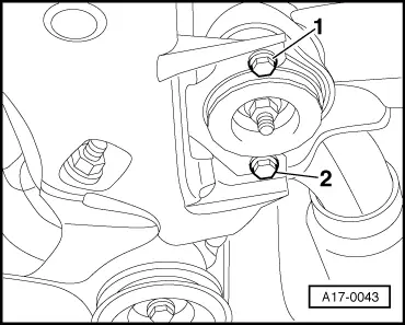
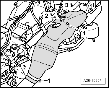
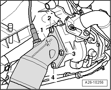
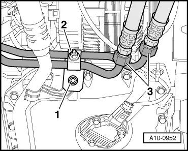
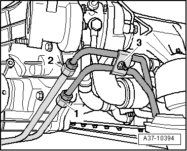
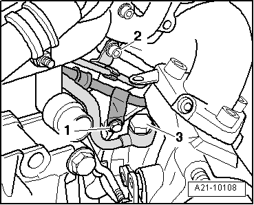
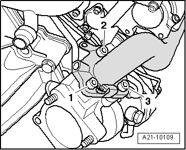
–  Remove bolts -1 … 3- and take out turbocharger.
Installing
Installation is carried out in the reverse order; note the following:
  Note
t  Renew gaskets, seals, O-rings and self-locking nuts.
t  
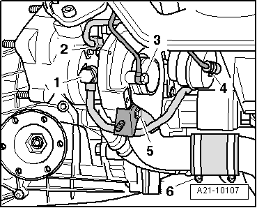
Fill turbocharger with engine oil at connection for oil supply pipe.
t  Hose connections and hoses for charge air system must be free of oil and grease before assembly.
t  Secure all hose connections with the correct type of hose clips (same as original equipment) → Parts catalogue.
t  Charge air system must be free of leaks.
t  Fit all heat insulation sleeves in the original position when installing.
t  Fit all cable ties in the original positions when installing.
–  Install exhaust gas temperature sender 1 -G235- → Chapter.
–  Install front exhaust pipe (right-side) with starter and main catalytic converter → Chapter.
–  Install gear oil pipes → Rep. Gr.34.
–  Install engine → Chapter.
–  Fill up with engine oil and check oil level → Chapter.
  Note
After installing turbocharger, allow engine to idle for approx. 1 minute and do not rev up immediately to ensure turbocharger is supplied with oil.
Tightening torques
  A21-10109
ComponentNm
Turbocharger to exhaust manifold60 1)2)
Oil supply pipe to turbocharger30
Coolant line to turbocharger35
Pressure line to turbocharger9
Oil return pipe to sump (top section)10
Hose clips (9 mm wide)3
Hose clips (13 mm wide)5.5
l  1) Renew bolts.
l  2) Coat threads and contact surface of bolt heads with high-temperature paste; for high-temperature paste refer to → Parts catalogue.


Charge air cooling - air flow > < Removing and installing turbocharger (left-side)