audi Workshop Repair Guides

Audi Workshop Service and Repair Manuals

Testing engine speed sender > < Testing control unit input variables
#Diesel direct injection and glow #plug system (4-cyl.)>06.97
Testing control unit input variables
Testing voltage supply for diesel direct injection system

The injection system is supplied with voltage via the diesel direct injection system relay -J322.

A prerequisite for making the main contacts at the relay -J322 is application of voltage via terminal 15 at the diesel direct injection system control unit. In other words, relay -J322 is only connected to earth (via diesel direct injection system control unit) when voltage is being applied to the control unit by way of terminal 15.

Test prerequisite:

  • ● Battery voltage OK
 
A97-0025

Testing voltage supply, terminal 15

  • ‒ → Pull diesel direct injection system relay -J322 out of relay frame 3 (auxiliary relay plate in E-box).
  • ‒ Connect up test box
  • ‒ Switch on ignition.
  • ‒ Activate 20 V measuring range.
  • ‒ Use hand-held multimeter V.A.G 1526 to measure voltage between following contacts:
 
A23-0019

Test box V.A.G 1598/18, socket

Test box V.A.G 1598/18, socket

38

1, 24, 46

  • Desired value: approx. battery voltage

Relay frame 3 in
E-box, contact

Test box V.A.G 1598/18, socket→

1

1, 24, 46

  • Desired value: approx. battery voltage 1)

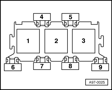
1) With engine code AFF and AFN, battery voltage must also be applied to relay frame 3, contact 1 with "Ignition off".

  • ‒ If the desired values are not attained, check cable connections.

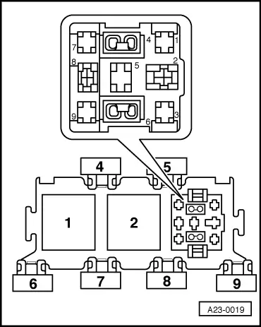
=> Current Flow Diagrams, Electrical Fault-Finding and Fitting Locations binder

Testing earth actuation of diesel direct injection system relay -J322

Test prerequisite:

  • ● Voltage supply, terminal 15 OK
  • ‒ Remove cover of E-box.
  • ‒ Switch on ignition.
 
A97-0025
  • → Desired value: Diesel direct injection relay -J322 at relay position 3 must be energised.

Note:

Clicking of the relay is not easy to hear and can thus be best felt by touching the relay.

  • ‒ If relay does not energise, switch off ignition.
  • ‒ Connect up test box => Page 23-37
  • ‒ Use auxiliary lead from V.A.G 1594 to connect following sockets of test box.

Test box V.A.G 1598/18, socket

Test box V.A.G 1598/18, socket

42

1

  • ‒ Switch on ignition.
  • Desired value: Diesel direct injection relay -J322 at relay position 3 must be energised.
  • ‒ If relay is now energised, replace control unit for diesel direct injection system -J248 => Page 23-38.
  • ‒ Switch off ignition if relay does not energise.
  • ‒ Pull relay out of relay frame 3.

Check following cable connections for short circuit to positive/negative and breaks.

 
A23-0019

Relay frame 3 in
E-box, contact

Test box V.A.G 1598/18, socket→

4

42

  • ‒ If applicable, eliminate cable break/short circuit.
  • ‒ If there is neither a cable break nor a short circuit, replace diesel direct injection system relay -J322.

Testing voltage supply, terminal 30

Test prerequisites:

  • ● Voltage supply, terminal 15 OK
  • ● Earth actuation of relay -J322 OK.
  • ‒ Connect up test box => Page 23-37
  • ‒ Use auxiliary lead from V.A.G 1594 to connect following sockets of test box.

Test box V.A.G 1598/18, socket

Test box V.A.G 1598/18, socket

42

1

  • ‒ Activate 20 V measuring range.
  • ‒ Connect hand-held multimeter V.A.G 1526 between following test box sockets.

Test box V.A.G 1598/18, socket

Desired value

45 + 46

approx. battery voltage

68 + 46

approx. battery voltage

23 + 46

approx. battery voltage

  • ‒ If desired values are not attained, check cable connections.

=> Current Flow Diagrams, Electrical Fault-Finding and Fitting Locations binder

  • ‒ If there is neither a cable break nor a short circuit, replace diesel direct injection system relay -J322.

Testing engine speed sender > < Testing control unit input variables