audi Workshop Repair Guides

Audi Workshop Service and Repair Manuals

Checking fuel gauge sender - vehicles with 4-cylinder engine > < Testing fuel pump (electrical test) - Vehicles with 4-cylinder engine
Fuel supply system - Diesel engines
Fuel supply system - four-wheel drive
Removing and installing fuel delivery unit - vehicles with 4-cylinder engine
 
G20-0014

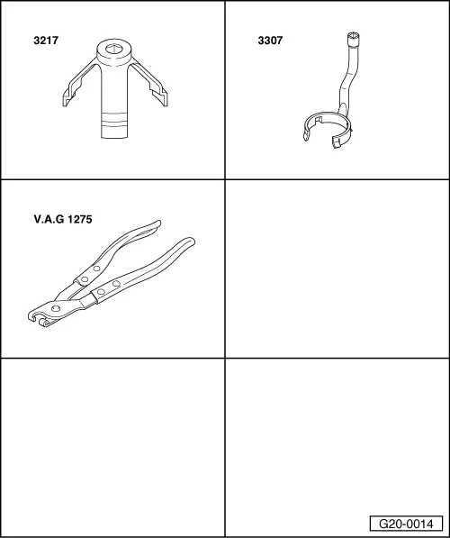
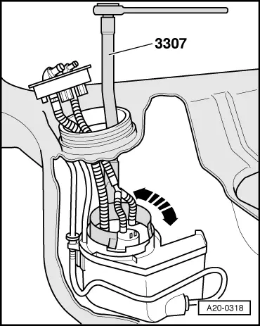
Special tools and workshop equipment required

  • ◆ Ring nut spanner 3217
  • ◆ Fuel pump spanner 3307
  • ◆ Hose clamp pliers V.A.G 1275
 
A20-0320

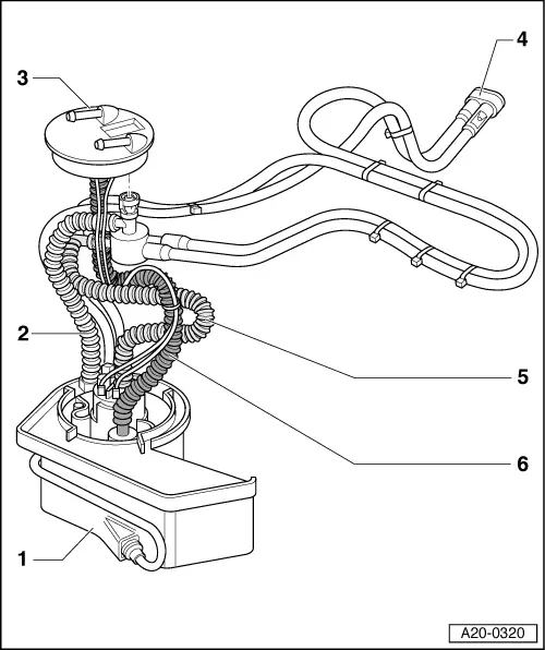
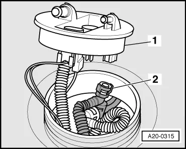
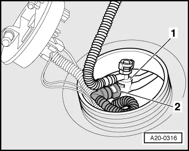
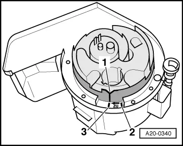
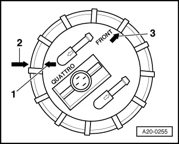
Note:

The illustration shows the correct routing of hoses inside the tank.

  • Baffle housing
  • Fuel return hose
    • ◆ From suction jet pump
  • Flange
  • Suction jet pump
  • Fuel hose
    • ◆ From fuel pump to suction jet pump
  • Fuel supply hose

Observe safety precautions.

Observe rules for cleanliness => Page 20-3.

Removing

 
A20-0190
  • ‒ The fuel tank must not be more than 3/4 full when removing the fuel delivery unit. Drain fuel tank if necessary.
    Procedure => Page 20-107.
  • ‒ Detach floor trim in luggage compartment.
  • ‒ Unbolt cover for flange.
  • ‒ → Disconnect fuel return pipe -2- and fuel supply pipe -3- from flange.
  • ‒ Release and unplug connector -1-.
 
V20-1026
  • ‒ → Remove union nut with spanner 3217.
  • ‒ Remove flange and seal out of opening in fuel tank.
 
A20-0315
  • ‒ → Pull fuel return hose -2- off inside of flange -1- (use uncoupling tool T40020 or press release tabs).
  • ‒ Unplug connector for fuel gauge sender on inside of flange.

 
A20-0316
  • ‒ → Disconnect fuel hose -2- from fuel pump at connection -1- for suction jet pump (use uncoupling tool T40020 or press release tabs).
 
A20-0334
  • ‒ → Press retaining tab, and at the same time pull the sender unit out of baffle housing in fuel tank -arrows-.

 
A20-0318
  • ‒ → Insert fuel pump spanner 3307 through opening in fuel tank and apply spanner to fuel delivery unit.
  • ‒ Using spanner 3307, turn fuel delivery unit anti-clockwise as far as it will go (approx. 15°), and take out fuel delivery unit.

Installing

Install in reverse sequence; note the following points:

Note:

Secure all hose connections with the correct hose clips (same as original equipment)

=> Parts catalogue

  • ‒ Place fuel delivery unit in fuel tank.
 
A20-0340
  • ‒ → Fit fuel delivery unit into outer section of baffle housing (in tank) so that notch -1- on fuel delivery unit is aligned with marking -2- on outer section of housing.
    • ‒ The fuel delivery unit should move down noticeably.
  • ‒ Apply fuel pump spanner 3307 and turn fuel delivery unit clockwise as far as it will go (approx. 15°). Notch -1- will then be aligned with marking -3- (bayonet fitting).
  • ‒ Insert fuel gauge sender into guide on outer section of baffle housing and press down until it clicks into place.

Notes:

 
A20-0316
  • ◆ Use new O-rings.
  • ◆ Ensure that O-rings are not trapped - use lubricant if necessary.
  • ‒ → Connect fuel hose -2- (from fuel pump) to connection -1- for suction jet pump.
  • ‒ Wrap fuel gauge sender wire once around the supply hose (in fuel tank) and connect at flange.

 
A20-0315
  • ‒ → Connect return hose -2- to inside of flange -1-.
  • ‒ Fit new sealing ring for flange in fuel tank opening (sealing ring should be dry).
 
A20-0255
  • ‒ → Fit flange into fuel tank; note correct installation position:
    • ‒ Installation position for vehicles with four-wheel drive:
      -arrow 1- must be aligned with -arrow 2-.

Note:

-Arrow 3- is for vehicles with front-wheel drive (can be disregarded).

 
V20-1026
  • ‒ → Tighten union nut with spanner 3217 (60 Nm).
  • ‒ Connect pipes and plug in the connector.

Checking fuel gauge sender - vehicles with 4-cylinder engine > < Testing fuel pump (electrical test) - Vehicles with 4-cylinder engine