audi Workshop Repair Guides

Audi Workshop Service and Repair Manuals

Testing fuel pump (electrical test) - Vehicles with 6-cylinder engine > < Overview of fuel delivery unit and fuel gauge sender - vehicles with 6-cylinder engine
Fuel supply system - Diesel engines
Fuel supply system - four-wheel drive
Testing fuel pump relay -J17 and activation - Vehicles with 6-cylinder engine
 
G20-0017

Special tools and workshop equipment required

  • ◆ V.A.G 1526 A
  • ◆ V.A.G 1527 B
  • ◆ V.A.G 1594 A
  • ◆ V.A.G 1598/30
    (engine code letters AFB with manual gearbox and automatic gearbox; engine code letters AKN with manual gearbox)
  • ◆ V.A.G 1598/31
    (engine code letters AKN with automatic gearbox)

Test requirement:

  • ● Battery voltage not less than 12.7 V

Test sequence

  • ‒ Remove storage compartment on driver's side:

=> General body repairs, Interior; Repair group 68; Storage compartments, covers; Removing driver's storage compartment

  • ‒ Operate starter.
 
A97-0024
    • ‒ → The fuel pump relay in 13-point relay carrier should pick up (no fixed position); this can be felt by touching the relay. The fuel pump should run (audible in boot - 2nd mechanic required).

A - If the relay does not pick up:

  • ‒ Test voltage supply to fuel pump relay.
  • ‒ Test activation of fuel pump relay
    =>Page 20-190.

B - If the relay picks up but the fuel pump does not run:

  • ‒ Test activation of fuel pump
    =>Page 20-193.
  • ‒ Test fuel pump (electrical test) =>Page 20-194.

Testing voltage supply of fuel pump relay

 
A97-0024
  • ‒ → Remove fuel pump relay from 13-point relay carrier (no fixed position).

 
A24-0298
  • ‒ → Connect voltage tester V.A.G 1527 B as follows:

13-point relay carrier,
(No fixed position)
Contact

Measure against

2

Engine earth

4

Engine earth

  • ‒ Switch on ignition.
    • ‒ The LED should light up.
 
A02-0021

If the LED does not light up:

  • ‒ Switch off ignition.
  • ‒ → Remove rubber seal from plenum chamber in direction of arrow-.
  • ‒ Remove plenum chamber cover -1- from the front.

 
A10-0761
  • ‒ → Remove cover for electronics box in plenum chamber -arrows-.
 
A97-0025
  • ‒ → Unplug diesel direct injection system relay -J322 (located in 3-point relay carrier in electronics box, plug-in position 3.
  • ‒ Test for open circuit and short to positive or earth in the following wiring connection:

13-point relay carrier,
(no fixed position)

Contact

3-point relay carrier
(electronics box)
plug-in position 3
Contact

2

5

4

5

  • ‒ Rectify any open/short circuit as necessary.

=> Current flow diagrams, Electrical fault finding and Fitting locations binder

If no wiring fault is detected:

  • ‒ Test voltage supply of diesel direct-injection system:

=> Diesel direct injection and glow plug system (TDI 6-cylinder); Repair group 23; Servicing diesel direct-injection system, Testing voltage supply of diesel direct-injection system

Testing activation of fuel pump relay

 
N28-0123
  • ‒ → Carefully lever off the retainer bar with a screwdriver -arrow-.

 
A10-0762
  • ‒ → Release retainer catch -arrows- and unplug connectors -1- and -2- from control unit.
  • ‒ Take out engine control unit.
Warning!
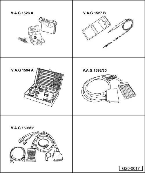
To prevent damage to the electronic components, switch to the respective measuring range before connecting the measuring cable and observe the test prerequisites.
  • ● Engine code letters AFB with manual gearbox and automatic gearbox
 
A23-0069
  • ● Engine code letters AKN with manual gearbox
  • ‒ → Connect test box V.A.G 1598/30 to the connectors which have been unplugged from the engine control unit (control unit remains disconnected).

  • ● Engine code letters AKN with automatic gearbox.
 
N23-0271
  • ‒ → Connect test box V.A.G 1598/31 to the connectors which have been unplugged from the engine control unit (control unit remains disconnected). Also connect earth clamp on test box to earth.
 
A24-0298
  • ‒ → Test for open circuit and short to positive or earth in the following wiring connections:

13-point relay carrier,
(no fixed position)
Contact

Test box V.A.G 1598/30


Socket

Test box V.A.G 1598/31


Socket

6

4/10

80

  • ‒ Rectify any open/short circuit as necessary.

=> Current flow diagrams, Electrical fault finding and Fitting locations binder

Testing activation of fuel pump

Requirements for test:

  • ● Fuel pump relay plugged in
  • ● Engine control unit connected.
  • ‒ Open fuse box cover on the left side of the dashboard panel.
 
A97-0119
  • ‒ → Pull fuse S 228 off fuse carrier (left row, 5th large fuse from the top).
  • ‒ Connect multimeter (voltage test range) between earth and left fuse contact.
  • ‒ Operate starter.
    • ‒ Specification: approx. battery voltage

If the specification is not obtained:

  • ‒ Check wiring

=> Current flow diagrams, Electrical fault finding and Fitting locations binder

If the wiring is OK and no faults are found in the tests up to this point:

  • ‒ Fit a new fuel pump relay -J17.

Testing fuel pump (electrical test) - Vehicles with 6-cylinder engine > < Overview of fuel delivery unit and fuel gauge sender - vehicles with 6-cylinder engine