audi Workshop Repair Guides

Audi Workshop Service and Repair Manuals

Servicing accelerator linkage - Vehicles with accelerator pedal module 02.99 ä > < Testing accelerator pedal position sender -G79 - vehicles with 6-cylinder engine
Fuel supply system - Diesel engines
Servicing accelerator linkage - Vehicles with accelerator pedal position sender
Adjusting accelerator position sender - Vehicles with 6-cylinder engine

Vehicles with manual gearbox

 
A20-0197

Requirement for test:

  • ● → Position of accelerator pedal stop: marking"H" or "HS" must be visible.

 
A23-0011

Note:

If accelerator position sender -G79 has been removed:

  • ‒ → Fit cable cam as shown.
  • ◆ In rest position the continuation of the spanner flat should intersect with the centre of the drilling -arrow-.
  • ‒ Install sender with cable cam already fitted.

Work sequence

 
A01-0061
  • ‒ → Connect the vehicle diagnostic, test and information system VAS 5051 or fault reader V.A.G 1551 and select engine electronics control unit by entering address word "01". When doing this the ignition must be on

=> Diesel direct injection and glow plug system (TDI 6-cyl.); Repair group 01; Self-diagnosis

 
→ Indicated on display:
Rapid data transfer     HELP
Select function XX
  • ‒ Enter "08" to select the function "Read measured value block" and confirm entry with Q key.
 
→ Indicated on display:
Read measured value block    Q
Enter display group number XXX
  • ‒ Press keys 0, 0 and 2 for "Display group number 002" and confirm entry with Q key.
 
→ Indicated on display:
(1...4 = Display zones)
Read measured value block 2    ⇒
    1    2    3    4
  • ‒ Check display in display zone 2.
    • ‒ Specification: 0.0 % (accelerator not depressed)
 
A20-0198
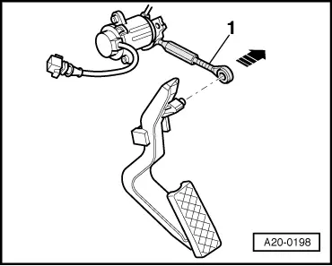
  • ‒ → Disengage eyelet of operating rod -1- from accelerator pedal -arrow-.
  • ‒ Remove anti-twist retainer (cable tie).
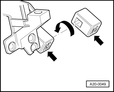
  • ‒ Turn threaded collar on operating rod.

Note:

The "100 %" display should be reached exactly when the pedal contacts the full throttle stop. If "100 %" is reached before the pedal contacts the stop, turn back the threaded collar accordingly.

  • ‒ After completing adjustment, carefully engage operating rod on accelerator pedal.
  • ‒ Check display in display zone 3.
    • ‒ Specification:
      0 01 00 (accelerator not depressed)
      0 00 00 (accelerator depressed)
  • ‒ Fit new anti-twist retainer (cable tie).

Vehicles with automatic gearbox

  • ‒ The adjustment procedure is the same as for vehicles with manual gearbox, except for the following points:
 
A20-0049
    • ‒ When making the adjustment, the accelerator pedal stop must first be fitted in the position for vehicles with manual gearbox:
      Marking "H" or "HS" must be visible.
    • ‒ With this stop installed, adjust full throttle position in the same way as for vehicles with manual gearbox (readout in display zone 2: 100%) .
    • ‒ → After completing the adjustment, install the accelerator pedal stop in the position for vehicles with automatic gearbox -arrows-:
      Marking "A" or "AG" must be visible.
  • Then check kickdown switch:
 
→ Indicated on display:
(1...4 = Display zones)
Read measured value block 2    ⇒
    1    2    3    4
  • ‒ Check display in display zone 3.
    • ‒ Specification:
      0 01 00 (accelerator not depressed)
      0 00 00 (accelerator depressed)
      0 10 00 (accelerator depressed past kickdown point)

Servicing accelerator linkage - Vehicles with accelerator pedal module 02.99 ä > < Testing accelerator pedal position sender -G79 - vehicles with 6-cylinder engine