audi Workshop Repair Guides

Audi Workshop Service and Repair Manuals

Testing fuel gauge sender - vehicles with 6-cylinder turbo engine > < Checking fuel pump delivery rate - vehicles with 6-cylinder turbo engine
Fuel supply system - Petrol engines
Fuel supply system - four-wheel drive
Removing and installing fuel delivery unit - vehicles with 6-cylinder turbo engine

Observe safety precautions

Observe rules for cleanliness
=> Page 20-5

Special tools, testers and auxiliary items

  • ◆ Ring nut spanner 3217
  • ◆ Fuel pump spanner 3307
  • ◆ Hose clamp pliers V.A.G 1275

Removing

  • ‒ Obtain radio code on vehicles with coded radio.
  • ‒ With ignition switched off disconnect battery earth strap.
  • ‒ Open fuel filler cap briefly, then close it again.
  • ‒ Drain fuel tank if necessary using fuel extractor V.A.G 1433 A => Page 20-53.

Note:

The fuel tank must not be more than 1/3 full.

  • ‒ Detach trim in luggage compartment.
 
A20-0190
  • ‒ Unbolt cover for flange on fuel tank under floor trim in luggage compartment.
Warning!
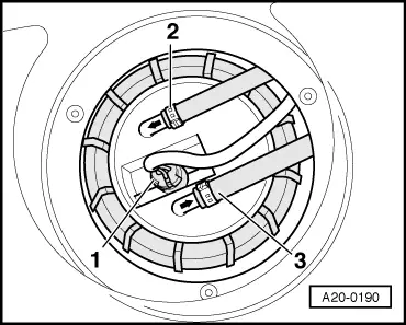
Fuel system is under pressure! Before opening the system place a cloth around the connection. Then release pressure by carefully loosening the connection.
  • ‒ → Mark the supply pipe -2- and return pipe -3-, then pull pipes off flange.
  • ‒ Release 4-pin connector -1- and unplug.
 
V20-1026
  • ‒ → Remove union nut with spanner 3217.
  • ‒ Remove flange and seal out of opening in fuel tank.
  • ‒ Unplug connector for fuel gauge sender on inside of flange.
  • ‒ Pull fuel return pipe off inside of fuel delivery unit flange (press release tabs).
 
V20-1101
  • ‒ → Insert fuel pump spanner 3307 through opening in fuel tank and apply spanner to inner section of baffle housing.
  • ‒ Using spanner 3307 turn inner section of baffle housing anti-clockwise as far as it will go (approx. 15°), and take out fuel pump with inner section of baffle housing.

Installing

Installation is carried out in the reverse order, when doing this note the following:

Note:

Secure all hose connections with the correct hose clips (same as original equipment)

=> Parts catalogue

  • ‒ Insert inner section of baffle housing, supply pipe and flange in fuel tank.
 
A20-0112
  • ‒ → Fit inner section of baffle housing into outer section of baffle housing (in tank) so that notch -1- on inner section of housing is aligned with marking -2- on outer section of housing.
    • ‒ The inner section of baffle housing should move down noticeably.
  • ‒ Apply fuel pump spanner 3307 and turn pump together with inner section of baffle housing anti-clockwise as far as it will go (approx. 15°). Notch -1- will then be aligned with marking -3- (bayonet fitting).

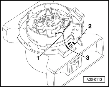
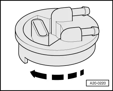
Note:

Baffle housing is shown without fuel tank for a clearer illustration.

 
A20-0220
  • ‒ → When installing, turn flange in a clockwise direction, as indicated in illustration.
  • ‒ Connect return pipe on inside of flange.

Note:

Lubricate O-rings with fuel or other lubricant.

  • ‒ Wrap fuel gauge sender wire once around the return pipe (in fuel tank) and connect at flange.

Note:

Lubricate the flange seal with fuel before fitting.

 
A20-0255
  • ‒ → Insert flange into fuel tank:
    • ‒ Installation position for vehicles with four-wheel drive:
      -arrow 1- must be aligned with -arrow 2-.

Note:

-Arrow 3- is for vehicles with front-wheel drive (can be disregarded).

 
V20-1026
  • ‒ → Tighten union nut with spanner 3217.
  • ‒ Connect pipes and plug in the connector.

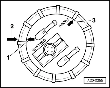
Note:

Ensure that fuel pipes are securely seated.

  • ‒ After connecting battery, enter anti-theft code for radio

=> Radio operating instructions

  • ‒ Close windows fully using electric window switches.
  • ‒ Then operate all electric window switches again for at least one second in the "close" direction to activate the automatic one-touch function.
  • ‒ Set clock to correct time.

Tightening torque

Component

Nm

Union nut for flange

60

Testing fuel gauge sender - vehicles with 6-cylinder turbo engine > < Checking fuel pump delivery rate - vehicles with 6-cylinder turbo engine