audi Workshop Repair Guides

Audi Workshop Service and Repair Manuals

Checking auxiliary signals > < Checking brake light switch and brake pedal switch
Motronic Fuel Injection and Ignition System (4-cyl) Turbo
Checking electronic engine power control (electronic throttle)
Checking clutch pedal switch -F36
 
G24-0023

Special tools and workshop equipment required

  • ◆ V.A.G 1526 A
  • ◆ V.A.G 1527 B
  • ◆ V.A.G 1594 A
  • ◆ V.A.G 1598/31
  • ◆ VAS 5051 with VAS 5051/1
  • or
  • ◆ V.A.G 1551 with V.A.G 1551/3 A

Note:

This signal is designed to prevent speed overshoots and jerkiness on switching from throttle open to throttle closed and vice versa when disengaging clutch. It is needed for the cruise control system.

Test sequence

  • ‒ Connect vehicle diagnostic, testing and information system VAS 5051 or fault reader V.A.G 1551 and select engine electronics control unit with "Address word" 01
    For this purpose, the ignition must be switched on.
 
→ When indicated on display:
Rapid data transfer    HELP
Select function XX
  • ‒ Enter "08" to select the function "Reading measured value block" and confirm entry with Q key.
 
→ When indicated on display:
Reading measured value block    Q
Enter display group number XXX
  • ‒ Enter "066" for "display group number 066" and confirm entry with Q key.
 
→ Indicated on display:
Read measured value block 66    ⇒
    1    2    3    4
  • ‒ Check clutch pedal switch in display zone 2.

Display zones

1

2

3

4

Display group 066: Signals to engine control unit

Display

xxx km/h

XXXXXXXX

xxx km/h

XXXXXXXX

Display

ACTUAL speed

Switch settings

SPECIFIED speed

Switch settings

Range


XXXXX0XX
XXXXX1XX

Specified value

XXXXX0XX
(clutch pedal
not pressed)

XXXXX1XX
(clutch pedal
pressed)

Note:

Value:
X = no meaning

If the display is not as described:

Checking switch

  • ‒ Remove driver's storage compartment.

=> General Body Assembly - Interior; Repair group 68; Dash panel; Removing driver's shelf

  • ‒ Unplug the connector from clutch pedal switch.
  • ‒ Connect multimeter between contacts 1 and 2 to measure resistance.
    • ‒ Specified value: approx. 0 ω
  • ‒ Operate clutch pedal.
    • ‒ Specified value: ∞ ω (no continuity)

If specified value is not attained:

  • ‒ Replace clutch pedal switch.

If specified value is attained:

  • ‒ Check the power supply.

Checking power supply

 
A24-0236
  • ‒ → Connect voltage tester V.A.G 1527 B as follows:

Connector
contact

Measure to

1

Car body earth point

  • ‒ Switch the ignition on.
    • ‒ The LED should light up.

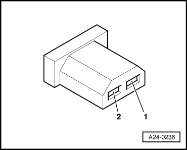
If the LED does not light up:

  • ‒ Check the wiring from contact 1 of the connector to fuse for open circuit:

=> Current Flow Diagrams, Electrical Fault-Finding and Fitting Locations

  • ‒ Rectify open circuit, if necessary

If the LED lights up:

  • ‒ Check actuation.

Checking actuation

  • ‒ Connect the V.A.G 1598/31 test box to wiring harness leading to engine control unit; the engine control unit should not be connected => Page 24-19.
 
A24-0236
  • ‒ → Check for open circuit and short to positive or earth in the following wiring connection:

Connector
contact

Test box V.A.G 1598/31
Socket

2

39

  • ‒ Rectify any open/short circuit as necessary.

Checking auxiliary signals > < Checking brake light switch and brake pedal switch