audi Workshop Repair Guides

Audi Workshop Service and Repair Manuals

Lambda probe heater Check for lambda probe -Z29 downstream of catalytic converter > < Lambda probe heater Check -Z19 for lambda probe upstream of catalytic converter
Motronic Fuel Injection and Ignition System (4-cyl) Turbo
Checking lambda control
Check lambda probe and lambda control downstream of catalytic converter

Note:

The lambda probe upstream of catalytic converter (Bank 1, probe 1) changes to Lambda 1. If this lambda probe is damaged, e.g. through contamination or overheating, the control value can be changed. Deviations from Lambda 1 is recorded by the lambda probe downstream of the catalytic converter (Bank 1, Probe 2). If these deviations are recognised downwards or upwards it influences the control upstream of the catalytic converter in such a way that it is generally raised or lowered accordingly.

 
G24-0024

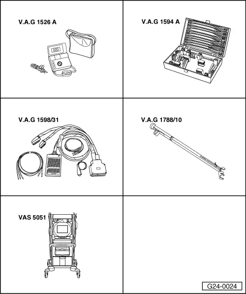
Special tools and workshop equipment required

  • ◆ V.A.G 1526 A
  • ◆ V.A.G 1594 A
  • ◆ V.A.G 1598/31
  • ◆ V.A.G 1788/10
  • ◆ VAS 5051 with VAS 5051/1
  • or
  • ◆ V.A.G 1551 with V.A.G 1551/3 A

Test requirements:

  • ● No leaks in exhaust system.
  • ● Coolant temperature at least 80 °C.

Test sequence

  • ‒ Connect up vehicle diagnosis, measurement and information system VAS 5051 or fault reader V.A.G 1551 and select engine electronics control unit with "Address word" 01 .
    For this purpose, the engine must be running at idle speed
  • ‒ Adjust speedometer V.A.G 1788/10 on accelerator pedal and increase speed to 2600 rpm.

Test conditions:

  • ● Engine runs at 2600 rpm.
 
→ When indicated on display:
Rapid data transfer    HELP
Select function XX
  • ‒ Enter "04" to select "Start basic setting" and confirm with Q key.
 
→ When indicated on display:
Basic setting    Q
Enter display group number XXX
  • ‒ Enter "030" for "display group number 030" and confirm entry with Q key.
  • ‒ Check Lambda probe status in display zone 2.

Note:

The "lambda probe status" indicates the condition of the lambda control and the lambda probes.

Display zones

1

2

3

4

Display group 030: Lambda status at idle

Display

X X X

X X X

Display

Lambda probe status, bank1, probe 1

Lambda probe status
Bank1, probe 2

Range

0 = off
1 = on

0 = off
1 = on


Specified value

1 1 1

1 1 0

Note:

If specified value not attained

Significance of 3-digit readout of display group 030

X

X

X

Display zones 1 and 2:

X

Lambda control 0 = not active, 1 = active

X

Lambda probe condition: 0 = not active, 1 = active

X

Condition of lambda probe heating: 0 = not active, 1 = active

Notes:

  • ◆ The first digit of the 3-digit display (heating) fluctuates between 0 and 1.
  • ◆ The lambda control of the lambda probe downstream of catalytic converter (B1-S2) is inactive without engine load.
  • ‒ Only continue the test if the display in display zone 2 has reached "110" at least once.

Checking lambda control after catalytic converter

Test conditions:

  • ● Engine continues running at 2600 rpm.
  • ‒ Press C key.
 
→ When indicated on display:
Basic setting    Q
Enter display group number XXX
  • ‒ Enter "037" for "display group number 037" and confirm entry with Q key.
 
→ Display readout:
System in basic setting 37    ⇒
    1    2    3    4
  • ‒ Check lambda probe voltage in display zone 2.
  • ‒ Check lambda correction value in display zone 3 and the diagnosis result in display zone 4.

Display zones

1

2

3

4

Display group 037: Diagnosis lambda control system

Display

xxx %

x.xxx V

x.xx

---

Display

Engine load

Lambda probe-
voltage
Bank1, probe 2

Lambda correction value
between
Bank1, Probe 1 and Bank1, Probe 2

Diagnosis status

Range

Test OFF
Test ON
Syst. OK
Syst. not OK

Specified value

13...40 %

0.100...0.950 V:

lower than 0.02

Syst. OK

Note:

If specified value is not attained: Evaluation

If "Syst. not OK" is displayed: Interrogate fault memory

Note on display zone 2:

The lambda probe voltage Bank 1, probe 2 should be kept as constant as possible. Strong voltage fluctuations indicate a damaged catalytic converter.

Interpreting display group 037

Display zone: 2

Possible causes of fault

Fault remedy

(constant
approx. 0.450 V

- Open circuit in line 4 between lambda probe and control unit

- Check basic voltage => Page 24-104

- Open circuit in line 3 between lambda probe and control unit

Greater than 0.950 V

- Short to positive in line 4 between lambda probe and control unit

- Check lambda probe wiring downstream from catalytic converter

Less than 0.100 V

- Short to earth in line 4 between lambda probe and control unit

(cont.)

If specified value in display zone 3 or 4 is not attained:

  • ‒ Perform test drive to free Lambda from any possible residues and repeat the test.

If specified value in display zone 3 or 4 is not attained, even after a test drive has been performed:

  • ‒ Replace the lambda probe upstream of catalytic converter -G39.

Note:

If the lambda probe voltage is OK and the lambda correction value is still above 0.02 even after test drive was performed it indicates an aged lambda probe upstream of catalytic converter.

Checking basic voltage

 
A24-0392
  • ‒ → Unplug 4-pin connector -1- (brown) to lambda probe upstream of catalytic converter -G130.

Note:

To gain access to the connector screw out coolant expansion tank bolts and swivel expansion tank aside. Fuel hoses remain connected.

 
A24-0094
  • ‒ → Connect multimeter between contacts 3 and 4 to measure voltage.
  • ‒ Switch the ignition on.
    • ‒ Specified value: 0.400...0.500 V
  • ‒ Switch ignition off.

If specified value is not attained:

  • ‒ Check the Lambda probe lines.

If specified value is attained:

  • ‒ Replace lambda probe downstream of catalytic converter -G130.

Check lambda probe wiring

 
A24-0392
  • ‒ → Unplug 4-pin connector -1- (brown) to lambda probe upstream of catalytic converter -G130.

Note:

To gain access to the connector screw out coolant expansion tank bolts and swivel expansion tank aside. Fuel hoses remain connected.

  • ‒ Connect the V.A.G 1598/31 test box to wiring harness leading to engine control unit; the engine control unit should not be connected => Page 24-19.
 
A24-0094
  • ‒ → Test for open circuit in the following wiring connections.

Connector
contact

Test box V.A.G 1598/31
Socket

3

68

4

69

  • ‒ Rectify open circuit, if necessary

=> Current Flow Diagrams, Electrical Fault-Finding and Fitting Locations

  • ‒ Check for shorts between the two lines.

If the wiring is OK:

  • ‒ Fit a new engine control unit => Page 24-23.

Lambda probe heater Check for lambda probe -Z29 downstream of catalytic converter > < Lambda probe heater Check -Z19 for lambda probe upstream of catalytic converter